QUESTION
I’m working on the reconstruction of an historical bridge that was built in the late 1800’s (two lane roadway). I’m curious about the live load that might have been used for design at the time it was built?
REPLIES
SlideRuleEra
Click through to my website below. I have the reference you need. Many engineering documents are free and out of copyright so I try to save the interesting ones.
Here are a few specific references on this subject:
A Pocket-Book For Bridge Engineers" - 1898, by J.A.L. Waddell - a “heavyweight” bridge design engineer from that time period. The 400 page book is in the public domain and can be downloaded in several formats.
In the late 1990s I had the opportunity to do some preliminary field engineering for the Rails-To-Trails Conservancy on a 1900 abandoned swing span steel rail bridge over a river in the middle of a swamp. The bridge had been designed and built by one of the well known bridge constructors of that time, Phoenix Bridge Company. We had the complete set of original drawings, hand drawn ink on linen, with fantastic detail shown. One example: Each of the wooden cross ties had a realistic, complete wood grain pattern detailed on it’s end… and no two patterns were the same.
In the 1920s the swing bridge had been permanently closed to river traffic, but we even had access to the bridge’s “key”… over four feet long and used to manually (no electricity then or now) swing the bridge open and close. The rail line appears to have been abandoned in the 1930’s Great Depression, with the bridge just sitting, more or less undisturbed since then.
The bridge was eventually converted to pedestrian traffic and is on a hiking trail now.
One of my old classmates gave me a book on bridge building in steel/iron that was written in the 1870s. I gave it to the professional association when I was on the Heritage Committee, in Vic’s name. They still have it on display. It was fascinating treatise on materials, connection, etc. They even had a portion discussing whether fatigue as a real possibility and whether it existed.
Added: In the pocket book referenced above, “… Just here the author wishes to state most clearly and emphatically, that to indorse (sic) the points asserted under this heading one need not to be a believer in the dotrines of Wohler and Weyrauch, and in the theory of the fatigue of metals because one’s common sense will lead him to proportion sections of bridge members in according with the foregoing views.”
WAG
I was told conversationally that the Live load used to design the Lions Gate bridge in Vancouver Canada was loaded dump trucks, bumper to bumper.
In 1900 a herd of cattle may have been an appropriate design load.
Does that correlate with the approximate strength of the bridge plus safety margin?
J.A.L Waddel also wrote a two volume set on bridge design, published circa 1916. I worked with someone in the 80’s who had a copy of it. He was very protective of those books.
Kunz wrote an excellent book on bridge design in 1915.
A few years ago I took over a design project ; replacement of a two span continuous plate girder superstructure that supported an elevated train line. Waddel and Kunz both came in handy with understanding the original design of the center pier and the elevated train viaduct.
A “herd of cattle” is likely a reasonable maximum load. The heaviest load (by far) ever put on San Francisco’s Golden Gate Bridge was a “herd of people”, on May 24, 1987:
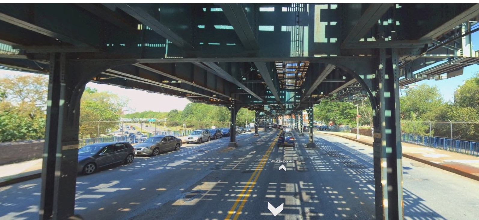
SRE - this is what it looked like prior to construction. The bridge is the along the blue railing. The bridge was built in 1940 (throughout the 80’s I worked for the man who designed it) but the train was built in 1915. I have to post a few more pictures to give a better understanding of how the old text books came into play.
The superstructure will be replaced in four stages. The first stage is done; that’s the right side of the photo outside of the train. The second stage is the left side of the photo outside of the train. Then we do the middle in two stages. One thing we have to do is hold up the train while the superstructure is replaced. The yellow I’s illustrate temporary girders that will support the subway structure. We’ll also replace the columns from about mid-height. You should be able to see a curved bracket between the columns and cross-girder. There were differences of opinion as to what it does - provide strength? provide stiffness? decorative only? - to me it’s providing stiffness. I was able to confirm that from Kunz’s textbook.
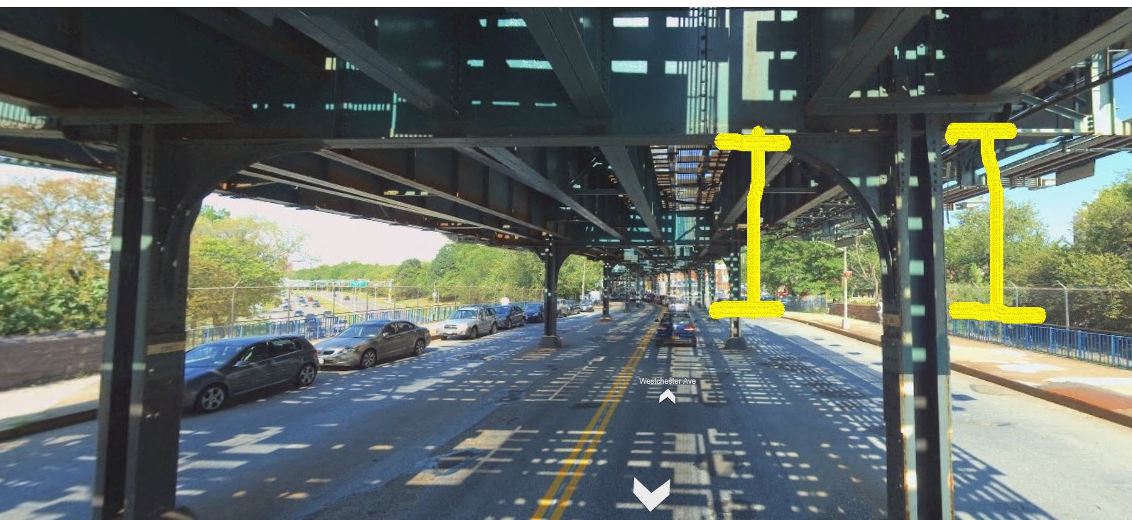
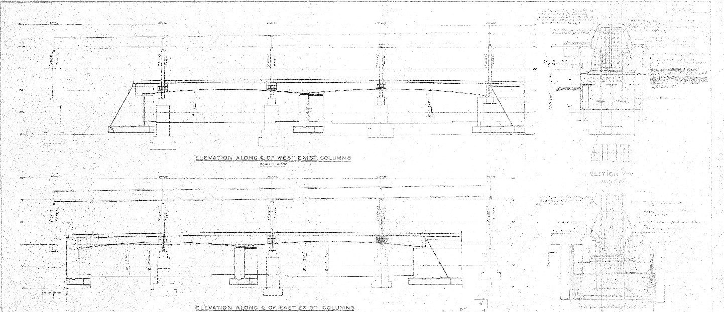
This is what it looked like before; this side has been replaced. It’s a 50-degree skew. The section of the highway was constructed in a cut, which also required underpinning the footings for the train structure columns. The bottom of the footings were at the same elevation as the top of the roadway. There was no underpinning procedure in the original plans, or at least none could be found. I imagine they built the bridge around the columns then transferred the loads to the superstructure. The center pier reinforcing is interesting; there’s more horizontal steel than vertical, by a ratio of 2.4. That was pretty much straight out of Bridge Engineering by Waddel (1916).
Thanks, Bridgebuster - I see a lot of riveted built-up girders, must have been quite a fabrication effort.
Out of curiosity, I checked to see what were the largest rolled beams available c. 1915.
W24 and W27, but max weight for these was only a little over 100 lb/ft.
Do I understand correctly… the 1940 bridge was constructed under the 1915 elevated RR?
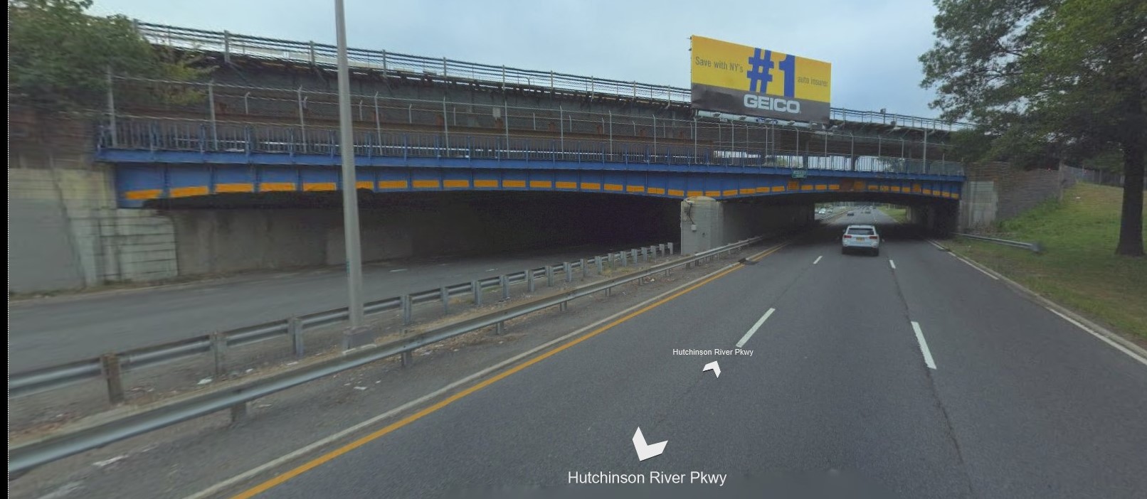
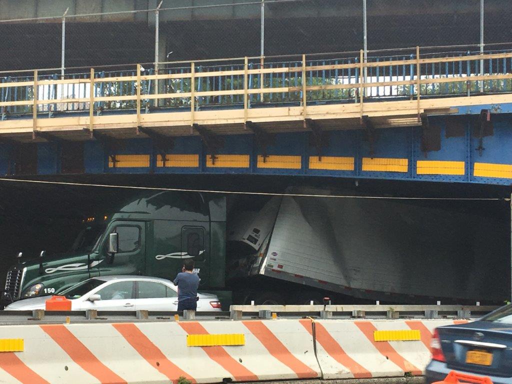
SRE- both structures are made of built-up riveted sections. The parkway was built in ~10 foot cut section under the train. Then the street below the train was raised about 5 feet. The bridge girders are 6’ deep at the bearings and about 4’ in the center. One reason the entire superstructure is being replaced is because of the low clearance over the parkway. It gets hit regularly by commercial vehicles even though they’re not allowed on that road.