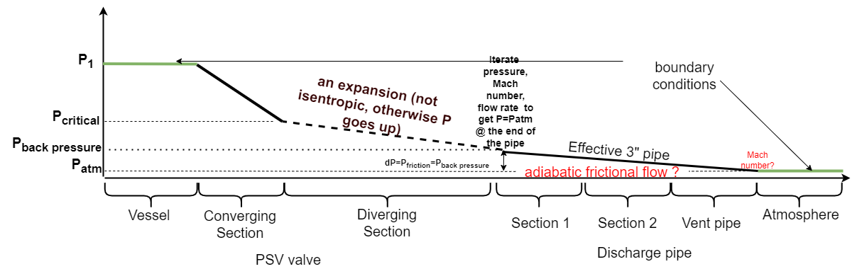
Steam from a boiler is fed into a pressure vessel at a maximum flow rate of m_in. The pressure vessel is equipped with a conventional psv. Let A_T and P_throat is the throat area and pressure, respectively. A_E and P_exit are then the area and the pressure at the PSV nozzle exit. A discharge line that terminates in a caisoon comes next to the PSV. The discharge line consists of 2 pipe segments with different sizes, as shown in Figure above. All numerical inputs are shown in green for clarity.
Critical flow or subcritical flow.
The downstream pressure is typically used to determine the flow regime. If P_downstream <= P_critical then critical flow, otherwice sub-critical. However, if we assume the flow through the converging-diverging nozzle is isentropic (as I model the PSV), then P_exit is always larger than P_critical. The aim here is to increase P_exit in order to decrease velocity and thus, friction.
On other hand, seems to me that oversizing pressure relief valves is a common practice. There are 2 posibilities here: 1. as soon we reach a given relieving pressure the valve starts opening slowly and keeps a certain position to discharge excess pressure (defined by m_in). 2. a batch-wise operation. multiple (full?) openings/closings. The first scenario is a steady-stede flow, while the second requires a dynamic simulation.
2. Back pressure from the vent pipe. If we are smoothly increasing pipe size between Section 1 and 2 that might correspond to isentropic expansion (fully reversible process). However, this assumption doesn’t look valid for the vent pipe. To my understanding the main pressure drop in the system occurs at the entrance of the vent pipe.
I would greatly appreciate if you could comment on these two points.
You seem to have a pressure ratio from the vessel to the atmosphere of about 13.
That’s going to guarantee critical flow unless the discharge pipe is extremely long.
If you are only trying to size the valve, then you can ignore the discharge pipe because, as you say, it can be oversized. In that case, you can simplify your problem drastically.
If, however, you are sizing all of these components together, to ensure overall system safety, then you need to model the complete discharge path to make sure the boiler is protected by its relief valve. Then you’re stuck with the whole problem.
I still think you can simplify the problem a little, though. Even if the NPS 2"+3"+8" path to discharge is complicated, they are all basically the same equation. You could replace that path with a single “equivalent” 3-inch pipe that is longer and has the same amount of back-pressure for the flow rates you’re expecting.
Iteration will be one strategy to getting to your goal. Start with the unconstrained discharge from the valve. Work out the flow using the simple model. That’s at least the boundary to your parameters - the flow can’t be higher than that.
Use that flow rate to determine the friction in the discharge pipe, then find the friction for 1/2 that much flow, then repeat for 1/3 the flow rate, and so on. Make that a simple plug-and-chug equation, and then stop worrying about the Darcy factor and go back to the valve’s discharge. There, now you have a way to adjust the downstream pressure = atmosphere + backpressure. Now you’re ready to iterate.
I don’t think the discharge pipe is long enough to make the initial flow non-critical. I do expect the transition from critical flow to non-critical flow to happen earlier because of back-pressure.
The model for a PSV is an isentropic converging nozzle, not an isentropic converging-diverging nozzle. In your model, are you seeing velocities > Mach 1 in the diverging section and outlet piping? That doesn’t happen in the real world.
The nozzle is usually Mach 1 at the critical pressure.
The transition from the nozzle critical pressure to the PSV outlet flange backpressure is treated as though a shock wave (Mach 1), an adiabatic pressure discontinuity.
Because a PSV is almost always too big (“choose the next bigger nozzle size”) a long duration worst case scenario will cycle the PSV. Scenarios with less flow will cycle the PSV more frequently.
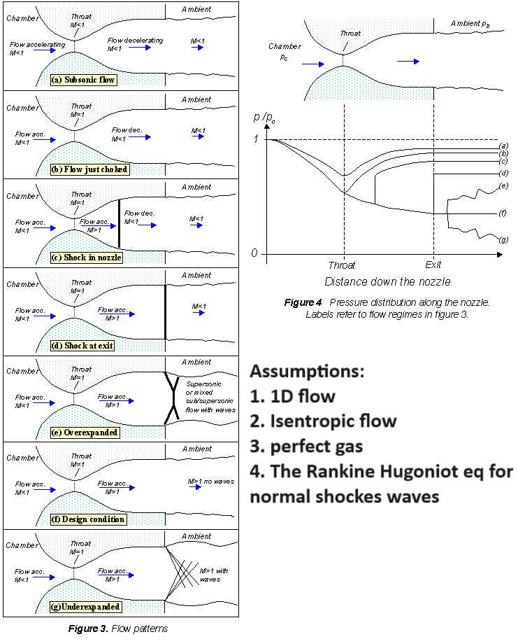
Thanks for the explanation, very useful as always. For me, this is a discovery. I was guided by rocket aerodynamics resources (e.g. Converging Diverging Nozzle ), where it is considered that the flow is isontropic in the diverging section. Figure below illustrates 7 possible cases and their pressure profiles along the nozzle.
I thought Case b) is applicable to my system (Mach number=0.195, Pexit=200psia @ PSV exit under isentropic assumption). If I understood correctly, you refer to Case c)
I understand. When one looks at a side-by-side schematic of a closed and open PSV it’s clear that downstream of the nozzle there is no diverging section:
It is more of an abrupt expansion to exit flange size, with an obstruction/restriction in the flow path above the nozzle, and a 90 degree turn.
I’ve never seen the Code in my company’s PSV sizing program. My simple program ends with the nozzle, and does not look at exit pipe and fittings. I don’t think my sophisticated PSV sizing program models exactly what happens between the nozzle and exit flange. It models the converging nozzle, and gets a flow. If flow is critical this is a maximum flow. Then, given this flow, it calculates the backpressure of the exit pipe and fittings at the PSV/exit pipe flange. There is a pressure discontinuity at the shock wave, so I am not sure what happens between the nozzle and exit flange can be modeled anyway.
Then, the program reports the pressure drop of the exit pipe and fittings as a % of PSV set pressure so one can determine if they need a conventional, bellows, or pilot operated PSV. The pipe and fittings exit condition are specified/known, and are usually ambient atmospheric conditions. This is why folks say to solve the pressure drop of the exit pipe and fittings “backwards”, the exit conditions are known and the inlet conditions have to be determined.
I think there are some thermodynamic rules that need to be followed for what happens across the shock wave, which can be used to determine the conditions at the PSV/exit pipe and fitting flange, but I’m not too familiar with those. I may look into that later.
Do you assume an adibatic (or isothermal) frictional flow in the effective discharge pipe?
Yes but only because it’s vastly simpler to do that.
You probably do not need the Mach number for your calculations. Not a common consideration in steam after all.
Another simplification that comes to mind - as the steam discharges it might transition out of saturation. Try to ignore this in your first iterations of the analysis, but don’t lose sight of it. Once you have the analysis run through and through the system without change of phase, then go back and check if the conditions at the exit still keep the steam 100% vapor.
Thanks, very much appreciated. However, I still don’t fully understand the approach you described. If flow is critical, all is clear. However, if flow is subcritical, the backpressure is above the critical pressure (above 40-60% of the relieving pressure for gases). No PSV is suitable for this. Still we would like to assess the backpressure. As the backpressure increases, the flow rate through the nozzle decreases (subcritical regime). This leads to less friction in the discharge line and thus leads to less backpressure. I am missing something …
I’m pretty sure it is an iterative process. Thank goodness for my software! I’ve never really had to calculate this myself. Discharge pipe and fittings are specified/known, mass flow is known from PSV capacity, atmospheric P is known. The pressure just inside the exit of the pipe should be 1 velocity head higher than atmospheric pressure, right? The fluid T should be calcuable based on P at any point. Take a look at Solving Adiabatic Compressible Flow.pdf I posted above. This is very relevant.
@SparWeb I’ve been thinking of buying an older Edition of White (now in 9th Ed.) mainly, and maybe Mott, at a good price, of course. You can get 7th Ed. White and older for under $20. If you know which edition has a worked PSV example as we’ve been discussing, please tell me which and I’ll target it. If not, I’ll roll the dice. Thanks!
Gee thanks for making me look old. I have a copy of White’s Fluid Mechanics at the 4th edition. :]
See chapter 9 in that version, especially Section 9.6, followed by the example problem 9.8. A couple of related problems can be found at the end of the chapter: 9.37 and 9.38 (probably others). It always seems to be air so for steam you’ll have to be inventive or simply do more research.
Thanks for the info! I picked up White’s 4th (1998) for $3.09 and Mott’s 4th (1993) for $2.61 from the same bookseller for a total of $15.21 with taxes and shipping.