Similar to this situation, what is the governing failure for limit state design, can we use its full capacity in plastic design with deflections over 20mm?
Would this be ok in a building rod bracing situation to have 20mm of opening movement?
Similar to this situation, what is the governing failure for limit state design, can we use its full capacity in plastic design with deflections over 20mm?
Would this be ok in a building rod bracing situation to have 20mm of opening movement?
#1 Yes
#2 No
Rowing… Trying to open a safe? 

Deflections need to be checked with unfactored loads or else the deflections will be ncorrectly multiplied by the load factors.
I am often fascinated by problems outside my discipline that look freakishly similar to problems in my discipline - and defined/analyzed/solved in different ways.
I look at your figure and it resembles the common “tension clip” structure used throughout aluminum aircraft. The way you pose your question, however, hints that you use a different frame of reference. Your first concern is deflections. That’s puzzling to an aero guy like me, who starts with strength allowables and later works out if deflections are of any concern.
Your diagram, too, is a clear indication that you are looking at something I don’t see. Your points B and B’ are not only inconsequential in the analysis that I would do, but distracting to me. And yet you have 3 answers from other SE’s who didn’t blink at it, so I assume in your frame of reference, they are meaningful.
The gross deflections that I would first turn to are vertical because the load is vertical, but your diagram doesn’t even show them. The secondary deflections due to the offset restraint apply deflections in a manner similar to what you drew, but if I drew it, I would also draw the deformation of the vertical member, which would bend back away from the clip.
How much of this is an illustration how different engineering disciplines can have different perspectives and priorities?
Sparweb,
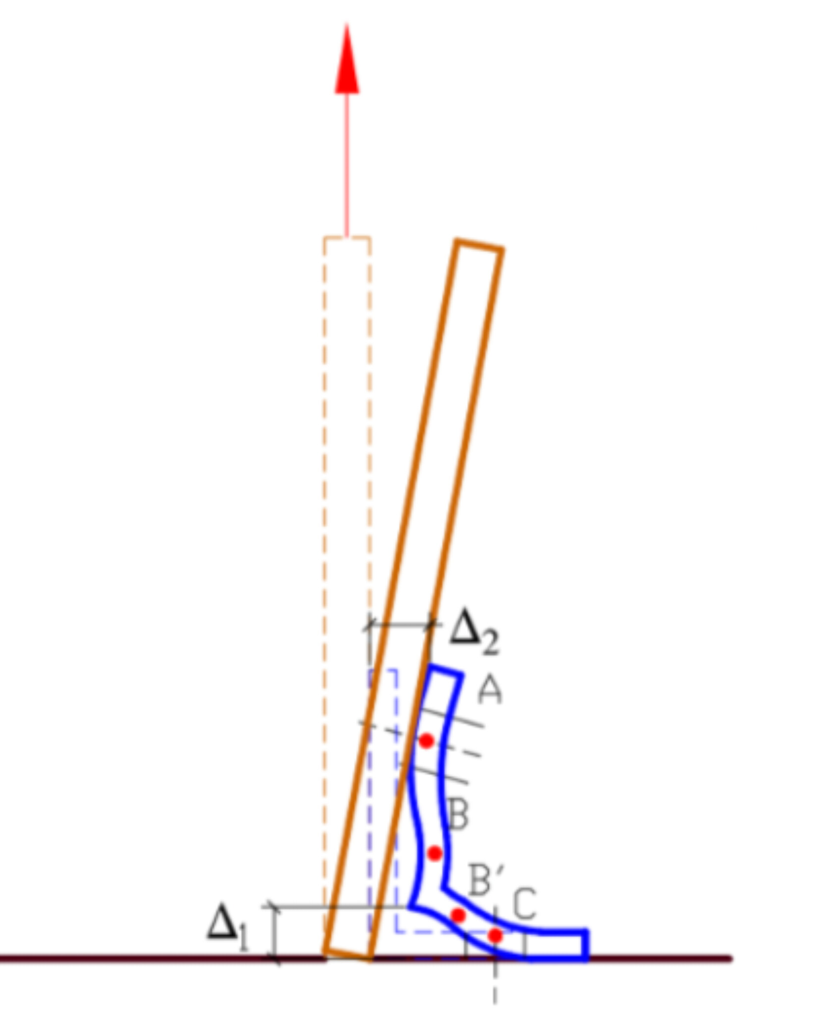
Points B and B’ are inconsequential in my view as well. But why should I blink at it? It has nothing to do with the question being asked. If those points are meaningful, it is not clear how. Same goes for points A and C. Point A appears to be the top of the vertical leg of the angle which has moved laterally a distance of Delta2. Point C appears to be the original position of the end of the horizontal leg. It is not clear how it moved laterally as shown by the blue outline, assuming it was welded at the bottom. The four red dots are not explained and not commented on.
You say vertical deflection is not shown. I believe it is Delta1 for the angle. It is not clear why the rod bracing manages to avoid the vertical movement. It should rise Delta1 as well, and should bend, convex to the right above the vertical leg of the angle. It appears the rod was not welded below point B or it would adopt the same curvature as the angle.
I would agree that the diagram is inaccurate, but did not feel inclined to comment on it in my earlier response. I answered the OP’s question rather laconically the first time. The ultimate capacity of the angle in bending is not related to deflection, but a deflection of 20mm under working load is unacceptable. In fact, I doubt that it is possible, assuming that the angle passed the strength test.
I doubt that our disciplines have different perspectives and priorities with regard to this example.
OK. Thank you for elaborating. If I’d seen that in a report in my own discipline, I would have thrown it out - and it seems you agree for all the same reasons.
Hard crowd at this site, I thought I did well to get a diagram in my post.
There are a few reports I am digesting to review my thoughts, the diagram is a picture from the report in the first link.
Basically the angle has to deflect to take load, and from the reports, depending on the report, the maximum load seems to be between 15-60mm. In JCU report they give the Permissible strength design load at 12mm, the other reports at different deflection levels.
If I was to take the maximum strength of the angle, I could be dealing with a lot of deflection, hence my question about deflections, normally in a moment plate if it exhibited such rotation deflection we would say it is simply supported, however in this type of connection is different, should it be a semi-rigid support in our analysis, in a bracing system that doesn’t matter, hence my rod bracing question. .
“Your points B and B’ are not only inconsequential in the analysis” you may find the first report interesting, I found it very interesting about how I would assume plastic hinge point vs what is tested.
https://scholarsmine.mst.edu/cgi/viewcontent.cgi?article=1267&context=isccss
Looking at the original post again, I believe we can use the full capacity in plastic design. The full capacity of the angle is Z*Fy. That is not the failure load, because as the load increases, the steel goes into strain hardening range. A deformation of 20mm or more occurs well past formation of the first or second plastic hinge.
We should not say that full capacity is the actual failure load; that contradicts the usual engineering definition.
Question #2 asks if 20mm opening movement would be okay? The answer is no, but it is reassuring to know we have that extra safety factor.
Agree that full plastic design could be used; however, I would be suspect of the connection being able to support the deflection at full plastic design. That’s a lot of prying!
No, 20mm is not acceptable both for lack of bracing and for connection issues.
@Rowingengineer…that’s why this site is head and shoulders above the other one! We don’t have to wade through the crap when, like you, you have guys like BAretired, SparWeb, PEinc and Msquared48 responding. These guys are engineers…not wannabe engineers! They are our peers, giving good feedback.