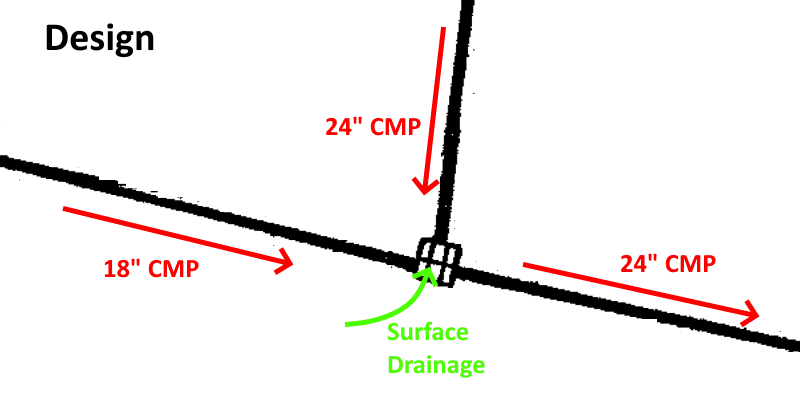
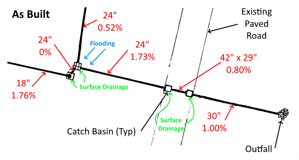
I am working on problems with a 36 year old existing residential corrugated metal pipe (CMP) storm drainage system. On one section, the as built installation differs from design in a subtle, but (I believe) significant way. During heavy rain there is flooding in this area. Here is the design plan:
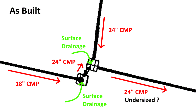
In my view, turbulence caused by having opposing flows “deadhead” into each other in one of the catch basins, limits flow thru the already marginally sized 24" outfall pipe.
Flow rates used to establish original design were never updated after the as-built change.
What are other’s opinions on the cause of flooding?
Because of existing houses, the easiest practical solutions appears to be replacement of the 24" outfall pipe with 30". Will taking this action improve drainage to reduce flooding?
There is certainly more resistance to flow in the as-built (more right angle turns), and yes, it would seem the outflow pipe is undersized as well.
I’ve been slowly getting our storm drainage fixed - the retention pond serving our house (driveway is a low point of the road) had an overlow lip that was about 12-18 inches too high, i.e. during storm flows, the water would pond in the roadway and overflow into our neighbor’s yard, while the level of the retention pond was still about 6" shy of the overflow lip. Finally got that fixed after arguing with the county for a couple of years, including photographs and threatening to take it to the local tv news station.
Now we are planning a midnight blacktop repair to fix an upstream catchment basin that was installed a couple inches above the roadway level, i.e. it never catches water. A bucket of pothole repair asphalt should fix it, now that the weather is hot and dry.
36-yrs old. i gather the original design did not consider “additional” housing? regardless, look for possible restrictions between 18" CMP & node where all 3 CMP meet. elevations do matter. just curious, the downstream 24"CMP is properly sloped? any level or rises in pipe elevation.
Not in my wheelhouse, but would having two surface drains instead of one impact flows? The sketch doesn’t really give an indication of whether the total drainage area or drainage flow (over time) has increased or not. A up-to-date dimensioned drawing/plot plan would be needed. Thus, my question. If having two surface drains instead of one and/or changes in drainage increases total flow, 30" may be too small. Is a new drainage study needed prior to developing the project scope? My $0.02.
Ben - Hope you get your drainage issues sorted out.
pmover - Housing in the development was completed many years ago, so nothing has changed recently. We (this is the development I live in) are in a subtropical environment (near Charleston, SC) and get frequent heavy rain downpours… and even more rain during tropical storms and hurricanes. There is no evidence of flow obstructions, when rain slows / stops the flooded area drains quickly.
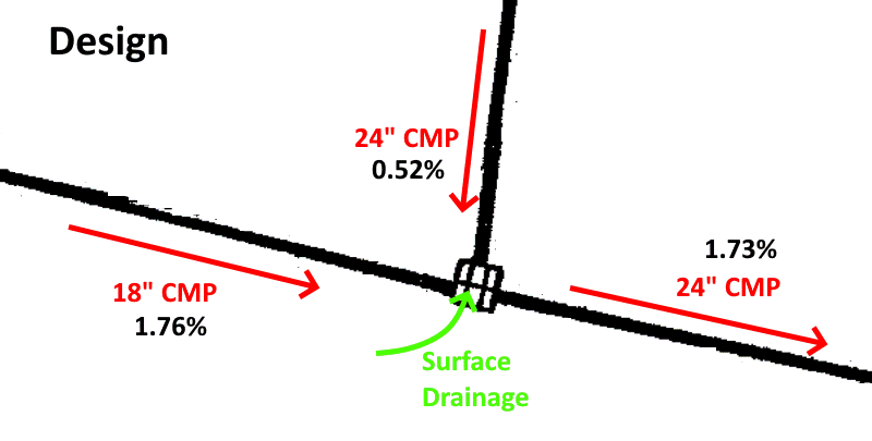
Design pipe slopes are pretty good, 1.73% for the existing 130’ long, 24" discharge pipe. Overall, with the high water table and relatively flat land, the drainage system works better than I would have expected.
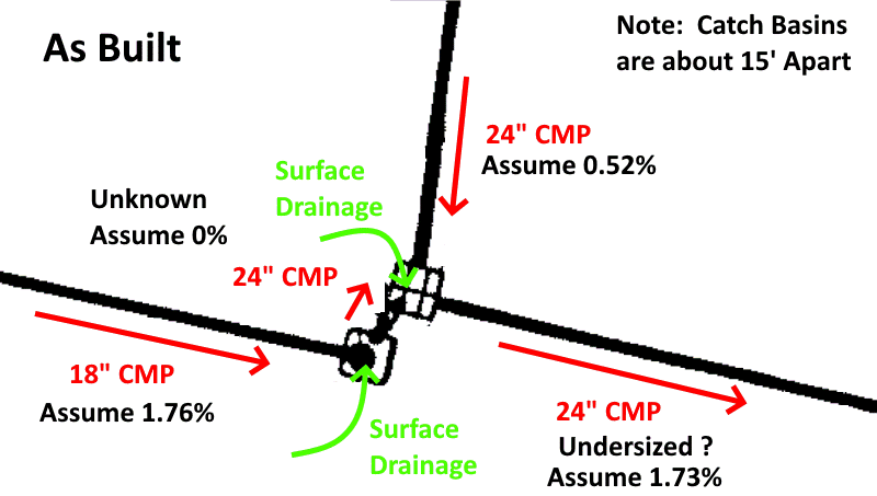
Latexman - Two surface drains possibly creating a problem is a good question. The two catch basins are about 15’ apart; adding surface drainage in addition to piping flow could increase turbulence. However, I’m not totally convinced that surface water flows into the catch basins during rain downpours… if catch basin inflow piping overloads outflow piping, water may actually be flowing out of the gratings. I had to deal with similar unexpected drainage flow patterns on my “day job” (before retiring).
CMP with 30" diameter should be adequate, 30" has nominal 156% of the cross sectional area of 24" CMP.
An updated overall drainage study will not be “in the cards” because of cost (not just cost of study but also implementing study’s recommendations). Since being asked to address the technical side of the community’s aging infrastructure in April, just getting this one pipe replaced will be a challenging and expensive project:
Construction work below the water table.
Pipe line parallel to and less than 4 feet from an existing slab-on-grade house
Destruction / replacement of landscaping features, etc.
Thank you, Mike. I’ve added the “design” pipe slopes to the sketches. Trouble is, I have no choice (without surveying current pipe invert elevations) but to assume “as built” pipe slopes are the same as design. Using that assumption, the only flooding explanation seems to be the energy loss (turbulence) caused by the inefficient (deadhead) pipe routing between the two catch basins.
What I hope to accomplish is the best possible “educated guess”, based on available info, that replacing the 24" with a larger (30") pipe will minimize flooding. I appreciate the input from all of you, a big step in making a sound decision.
Also, will be looking at in-place lining the existing 24" outfall pipe to increase flow capacity by having smoother pipe walls with minimal decrease of pipe inside diameter.
Hydraulic jump… I think you have the answer - many thanks, Mike.
So, even if the 24" outfall pipe is replaced with a 30" pipe, could flooding continue since improper catch basin inlet piping (causing hydraulic jump) would remain unchanged?
SRE, I had the same thoughts. I have a lot of experience with “pipe flow” but hardly any with “open channel flow”, so I was thinking, who could help? Well, my first thought was @katmar. Maybe he’ll come along and reply.
Thanks, Latexman. I never did any open-channel flow work either, other than some basic ditching next to roads. Since the system is flooded, assumed low head (a couple of feet), full-pipe flow and used Hazen-Williams to get an approximation that the outfall pipe cannot handle the input… but that’s as far as I could go.
Looked at the drawings to see if there is any (easy) way to reroute the piping for more efficient junctions… not looking good. Available community “common ground” is too limited in this area. Explains why the builders (36 years ago) added the second catch basin and “hoped for the best”.
Well, you would have to check the 24” pipe capacity with the reduced velocity after the jump to see if the 24” would work, and even a 30”. Would be tricky, but could be done…. After the jump, the water level in the pipe, whatever the size, will be higher due to the reduced velocity.
My experience is also mainly with pumped flow, but a grossly disproportionate fraction of the serious piping problems that I have had to solve have been of this “gravity flow” type. And almost all of them have been associated with problems in air or vapor removal, so that is where I would start looking.
The 24" discharge pipe with a slope of 1.73% should give a flow rate of around 10,000 GPM and a velocity of 6 ft/second. I would expect this flow rate to flush any air out of the pipe very quickly. But I would still check the discharge point to see that there isn’t something that could restrict the air removal - for example discharging into a much larger pipe with its discharge hydraulically sealed by discharging below the surface of a body of water.
You have not mentioned the final discharge point at all. Any back pressure there would impact on the capacity of the line.
A capacity of 10,000 GPM sounds large, but it should be checked against the area that the drains service and the maximum rate of rain fall.
I calculated rainfall intensity needed to produce 10,000 gpm (1337 cfm) in the 24" outfall pipe:
Design drawings call for that pipe to drain 5.50 acres (roads only, no grassy areas). However, the As-Built drawing shows two added catch basins upstream that add an estimated 1.5 acres of surface drainage from grassy areas… total area drained by the 24" outfall pipe = 7.00 acres (305,000 sq ft).
Note: Design calcs were never updated, both design and as-built drawings are for 5.50 acres of drainage area.
Do the math… 1.58" of rain in 30 minutes produces 10,000 gpm. A 2 year rain event is a nominal 1.60" in 30 minutes.
For 15 minutes duration, 0.79" of rain produces 10,000 gpm. A 1 year rain event is a nominal 0.99" in 15 minutes.
Both of these scenarios are likely… we had at least two and maybe three days in July 2023, with this type intensity, or higher. Flooding occurred on at least one of these days. Flooding has been going on for years.
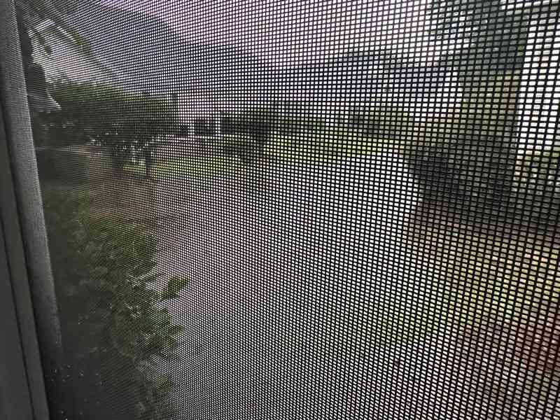
For reference, here is a photo taken by an affected resident (thru screen wire) during flooding:
Thanks for the additional information @SlideRuleEra. It is always re-assuring when the design requirements match the actual performance reasonably closely.
Based on your numbers it does appear that the 24" outflow line is simply too small. It would probably be worth checking the levels in the two catch basins on the sides of the paved road to see if there is any imposed back pressure during flooding. But that would mean not being able to do anything until it floods again and you can do an inspection.
The calculations that I have done were using Manning and also Darcy-Weisbach, but I do not have roughness coefficients for these models that I am confident of for corrugated steel pipe. It would be best to get the calculations checked by someone with more relevant experience.
I did check the impact of the entrance losses where the water enters the 24" line. These will come into play when the level in the second catch basin rises above the top of the pipe. Changing the entrance from a flush 24" entry to a 30 degree cone with a 36" mouth would decrease the losses by 4 or 5 inches WG, but from the photo that you posted it looks like the back-up is more than that and while this would help in some lesser rain events it would not be the complete answer.
Unfortunately it does look as though replacing the 130’ of 24" pipe with 30" would be the correct solution.
Thank you, @katmar, when our next heavy rain comes, I’ll try to check the downstream, paved road catch basin water level (if safe to do so… in summer, lightning almost always accompanies downpours). Seem like every time I look at these drawings some new unsupported change between design and as-built drawings comes to light. No wonder there are problems.
At the routine monthly meeting later this afternoon, will be briefing community residents about our findings. How this information is received will be interesting.