Something has been bothering me lately regarding the deflection of a beam with equal and opposite moments applied at each end. Maybe somebody can tell me where I am wrong.
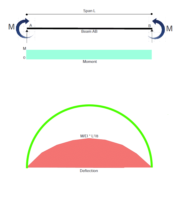
Following through, using Conjugate Beam Method, I find the deflection at midspan to be ML^2/8EI, which is a parabolic curve. But with equal moment throughout the span, shouldn’t the beam bend into a cylindrical curve?
Any comments would be welcome.
ET15.pdf (56.1 KB)
BA - I don’t know the answer, but “may” have a clue on where to look for it:
The sketch shows simple supports at each end of the beam. But with the only loading being moments, these supports have no load on them… which seems odd. To me, with no force applied, the beam ends cannot move (per Newton’s third law)… the beam can only rotate at it’s stationary ends.
With these conditions, seems the beam can only deflect… which it does, with maximum deflection at midspan.
If the beam was to bend to a cylindrical curve, and the beam ends cannot move, beam length would have to stretch in length to (AB) x (Pi/2), shown in green:
BAretired,
Are you using double integration to solve your beam? Double integration is not a precise and correct solution to beam deflection. The calculus requires the beam elements to move straight up and down, which is not what they do when you apply moments to the ends.
For most practical applications, it is good enough.
1 Like
SRA - It’s true that there are no reactions; the system is in balance with just the applied loads. There is also no shear across the span. Pin/roller supports are necessary to prevent the beam from wafting into cyberspace, but the roller supported end is free to move horizontally to accommodate the change in length when the beam bends.
It just seems odd to me that a beam which has a constant moment throughout its length, hence a constant curvature, would bend in the shape of a parabola instead of a circular arc. I believe this is a case of cylindrical bending. But we are dealing in very small angles where theta is so small that it is taken equal to sin(theta) and tan(theta), so the error in assuming a parabola is not very significant.
I’m a bit rusty on Newton’s third law, but I don’t believe it prevents a roller support from rolling. If both supports were pinned, I would agree with you.
Anyhow, thanks for the response, SRA.
Welcome back, RD; it’s been a while since we have heard from you.
I did not use double integration to solve the beam; I used the Conjugate Beam Method, but I believe the results are identical.
I had not considered the fact that my applied loading caused the beam to deflect at an angle to the vertical. I believe you have found the solution to my quandary, for which I thank you.
BAretired,
When I was college, I took a welding course where we measured the bending of a plate with a weld bead. We are asked to explain it.
I could not make sense of the double integration, so I pulled out my book and I read up on beam theory.
RevDesigner,
I should have done the same, RD. I had forgotten that the exact formula for curvature is different from the expression commonly used in beam theory; it involves the term [1+(dy/dx)^2]^3/2, and when dy/dx is very small, its square is negligible. Thanks for the reminder.
The easy solution is that the BM in the beam is constant and the only structures formula I bother remembering is M/I=s/y=E/R
So if M, I and E are constant so is the curvature. So it is a circular deflection.
Hmm, good discussion. Would not think about it until you pointed it out, BA.
Should be able to demonstrate that to yourself with a thin piece of wood or a small diameter rod.
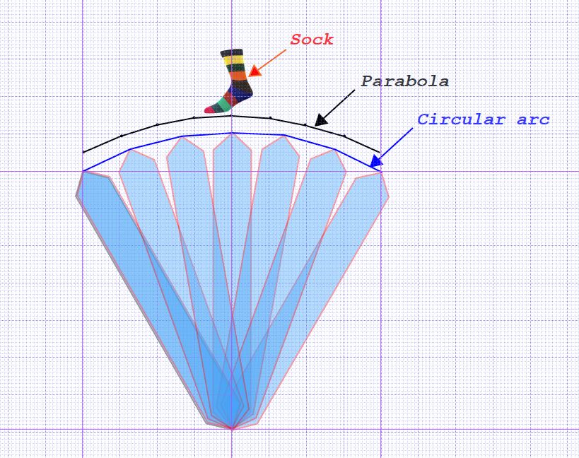
It’s easy to demonstrate that the rod bends, but the difference between a parabola and circular arc is not readily seen by the naked eye.
Put a sock on it , BA, and you will see the circle! 

You were right Mike. Now I see the circular arc!