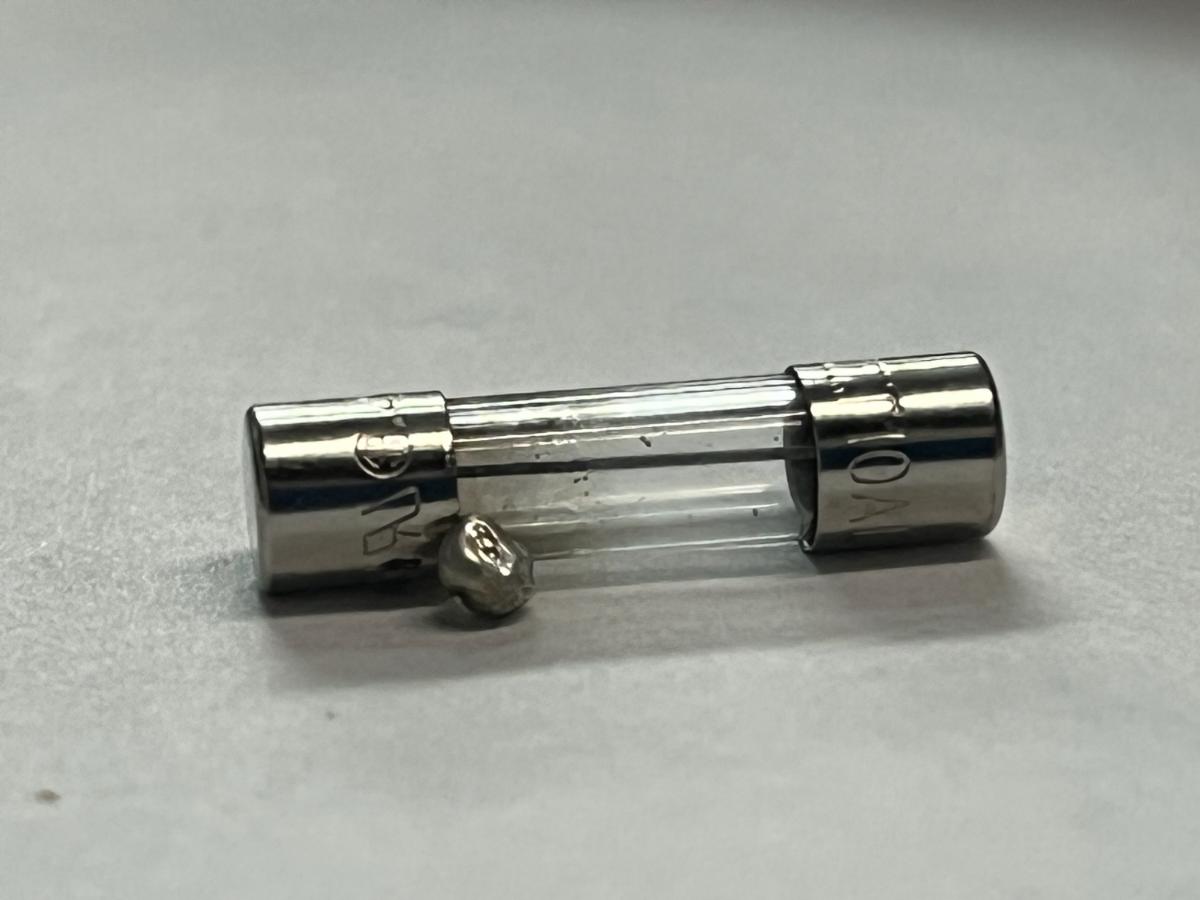
The attached picture shows a 10 amp, slo-blow fuse that was in a control panel that we are currently using to run stress testing (continuous cycle testing) on a hydraulic actuator. The fuse is on the feed to a 1/2 hp 115vac cap-start motor, and at 10 amps is a bit undersized (the original design was for 220v service, and this dumb mech engr. didn’t think to upsize the fuse for lower voltage applications). The fuse blew after probably 200k start cycles, and has been replaced with a 15 amp fuse.
But what I found curious is the blob of ejected fuse metal near the one metal end cap. I thought fuses were not supposed to be able to release molten metal, by design and by UL standards? Or is that just a “shouldn’t” kind of requirement, rather than a “must not”?
I’m not sure of “molten metal” release by fuses . . . sure is a shiny surface w/ no carbon. appears like too much molten metal than what is what is mfg to melt inside the fuse.
Cannot tell, but did the melted metal come from inside the fuse? a loose metal shaving, perhaps.
Also, it’s weird, but what looks like leftover fuse wire inside the glass tube is just an artifact of the lighting, it disappears when you use natural sunlight to look at it.
“Ejected” conjurs up mental images way more dramatic than the photograph.
I wonder how the ends of the cartridge were assembled. Some have a double-layer cap at each end and a hole drilled in the end of the inner layers. In these, the fuse element is led through the holes at either end, secured with solder (on the outside) and then the joint is covered with the outer cap. The gap I think I can see between the glass tube and the walls of the visible cap is typical of that sort of construction.
If your fuse was built that way, then the escaping metal could be solder from the joint that had already melted and dribbled out from chronic heating long before the fuse blew.
I’m with @Pmover on this one. It looks like a solder ball from “somewhere else” that happened to land on this fuse. Touch it with a hot solder iron tip and see if it melts to confirm it’s actually solder and not something else.
I can see the fusible element still inside your fuse so I assume the fuse blew simply by breaking the element in one place (the left end as seen in the photo) and not be “liquefaction”.
I peeked inside a glass fuse here, no solder used in its manufacture. The fusible link inside is probably not soldered to the cap, probably more like welded or brazed so that joint won’t be the weak link. Definitely isn’t that much solder inside!
Slow Blo fuses have two elements.
One is the conventional wire type similar to a single element fuse, but rated to blo at higher than the fuse rating. This blows on short circuits.
The second element is a low melting point alloy surrounded by a heating element.
This melts on overloads but has a time delay due to the heating action.
As far as metal leaving the fuse cartridge, that shouldn’t happen, but;
“Stuff happens.”
Thanks Bill, I guess you are correct (stuff happens) - I can’t find anything in the UL standards that say “must not”. Not a big deal, the metal stayed contained inside the fuse holder block, so no damage done beyond a slight stain where the metal was semi-soldered to the sheet metal clip of the fuse holder.
Zeus, yeah maybe not so much ejected as dribbled. And yeah, there are visible gaps between glass and metal cap on these fuses, but these are not the through-lead style you mention, just plain metal caps.
Spar, no, no other source of solder in the vicinity, see previous posts, also no fusible element is visible inside the tube when held up to natural light, what you see is an artifact of indoor fluourescent tube lighting - again see previous posts. This was a 10A fuse, the kind with a wire-wound element like WaRoss mentions. Quite a big chunk of wire relative to the fine wire in a 1A and 2A fuse (which we also use for other devices).
Pondering this matter, wonder if weighing the blown fuse w/ molten metal and comparing to similar fuses can shed any further insight. Yeah, a gram scale will be needed. Not worth the exercise though . . .
What @waross said. In addition there are multiple fuse types, including the sand or other inert material filled fuses that cost a bit more but are less likely to shatter or let the contents out when they go off. It’s not unheard of for the glass to shatter on cheaper fuses in some applications.
Oh, and pmover - the weight of the blown fuse and metal blob is nearly equal to the average weight based on a sample of 5. So, pretty sure the metal came from the fuse.
Update - we’ve blown a second fuse in aboout a week (some 15k more starts). I plan to map the startup current again with a PicoScope (thanks again Gunnar, may you RIP) and current clamp, but prior tests gave a peak starting current pulse at around 50 amps for a 9.8 run current. So, back down the rabbit hole - NEC allows oversizing a slo-blo fuse up to 20 amps, we’ll try that next (have to go to a midget fuse vs. the 5mm glass case, making it all a bit more expensive…). To go higher than that (up to 30 amp rating) under NEC rules requires use of a class CC fuse at even higher expense…more testing is going to be needed.
Interesting situation w/ the high current draw at startup. Good to record startup amp draw and conduct further analysis. it will be good to know the startup amp draw and for how long.
Ok, did some digging again. 50 amps was during a high-temperature test where we ran the motor at worst case load in an enclosed and insulated space. 40 amps is what this current long-duration, high-cycle test is pulling on a fairly cool day in the shop. The start switch kicks in, and amperage quickly drops, within about 3 60 Hz cycles. This lower amp test however is doing many more cycles than we ever did in the temperature stress testing. 15 amp glass-tube fuse has been swapped out for a midget fuse at 20 amps rating, and testing continues.
You may, from time to time, get a much higher first cycle peak current.
This may partially melt the fuse alloy. Enough cycles and it finally fails.
I agree with the 20 Amp fuse choice.
That was my thinking too, thanks for confirming Bill. I’m hesitant to jump straight to the overkill solution of a 25 or 30 amp CC (controlled current) fuse, but at the same time want to minimize nuisance trips for field use.