By @stevenal
Assuming ratios and impedances match, yes. An interesting paper:
Figures 10 and 11 on page 13 are the ones of interest.
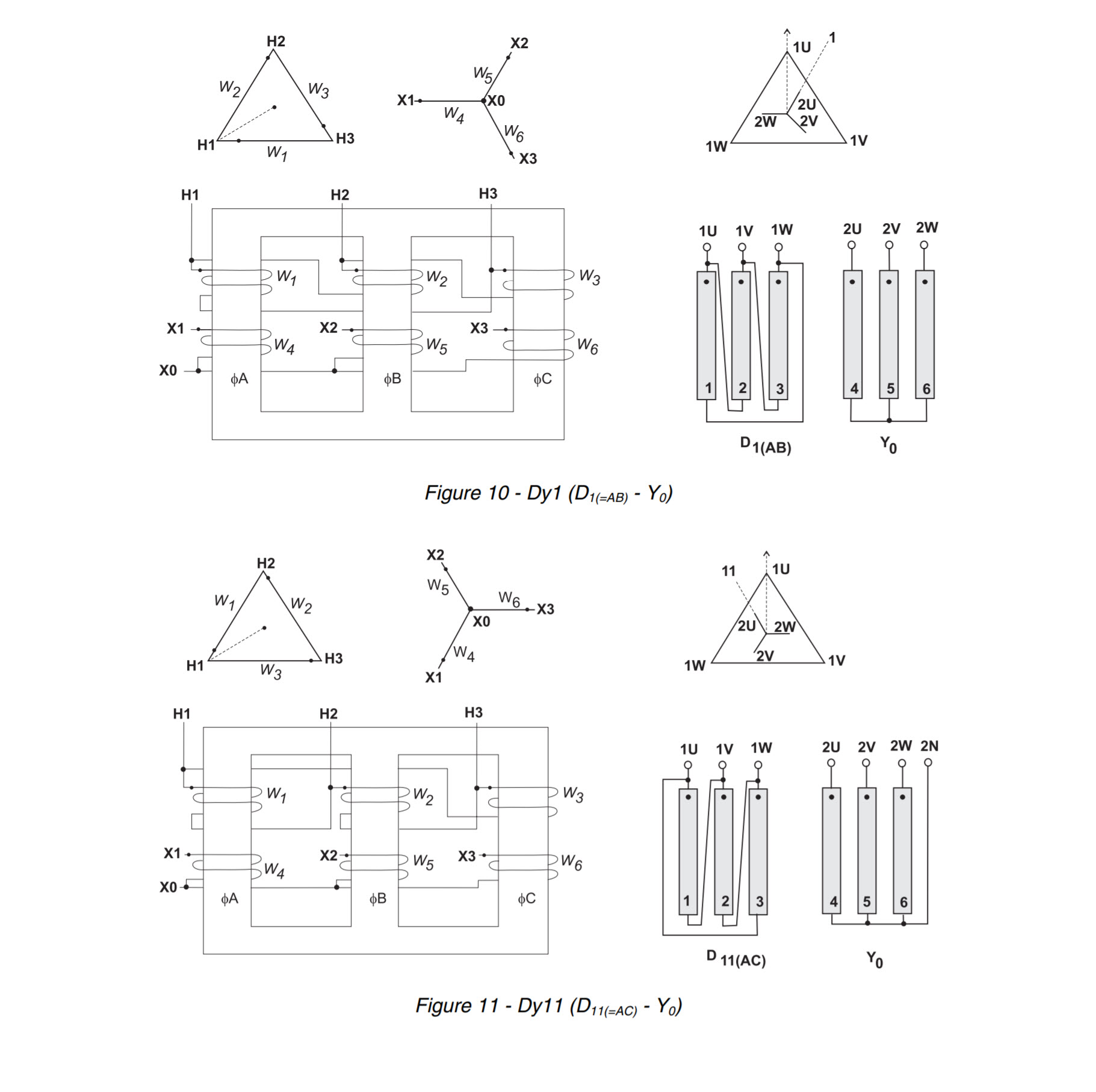
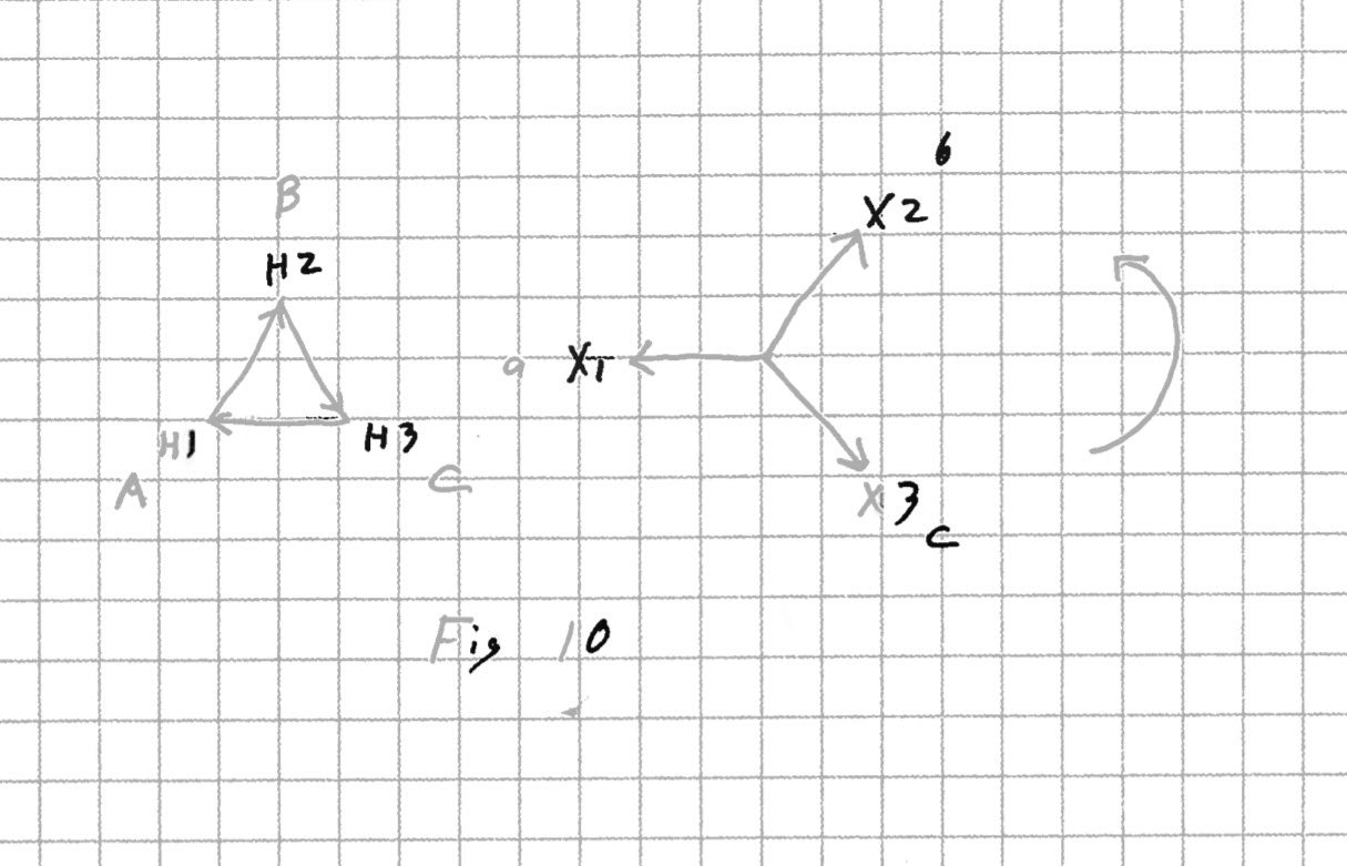
Let’s use the figures and bushing numbering arrangements shown on the left. Beginning with Fig 10, write A next to H1, B next to H2, C next to H3, a next to X1, b next to X2 and c next to X3. These represent the system phases, and ABC (abc) rotation is assumed. To represent the rotation, draw a semicircle next to the phasors with an arrowhead pointing in the CCW direction. Fig 10 is done.
Use a separate piece of paper for Fig 11. Redraw all the lines heavily, then draw C next to H1, B next to H2, A next to H3, c next to X1, b next to X2, and a next to X3. To represent ABC rotation, a CW arrow is needed. Turn the page with Fig 11 over, left to right. Hold up to a light if necessary. If done properly, all the system phases will be in the same locations on the two figures, with both rotation arrows pointing in the same direction. Connect the system phases to the bushings as shown and your transformers will parallel. To be safe, always test voltage across an open switch before completing the parallel. By rotating the figure, you can see that any pair of high side connections can be rolled as long as the corresponding low side pair is rolled as well.
So was the DY11 converted to a DY1 by means of changing the external connections? If you look at DY? as referring to the system phases, yes. I prefer to see the DY? designation as an indication only of the internal connections. I can then more easily see that any DY transformer can be installed so the secondary is + or - 30 degrees, + or - 90 degrees, or + or - 150 degrees.
I hope you found this explantion useful.