CNC Router Table Design References

Hi,

Does anyone know of books, design guides, or other such material about the general features and design of machine tooling, particularly machinery suitable for CNC control?
More specific than Shigley, I mean.

Subjects that I want to look at more rigorously:

  • Stiffness
  • Inertia
  • Heat dissipation

The kinds of things that make a machine with 90% good components turn out sloppy junk parts because of mistakes in the other 10%.

If someone wanted to build their own CNC router, they could always look at the machines around and duplicate them. There are several machines I have looked at to learn from. But I’m convinced it’s not that simple (consider the reputation of machinery made in China when it’s copied without understanding the principles of operation). I also believe there is a science to this hiding in the background. I’m not having any trouble making sense of the general information I can find on the internet, but it’s pretty shallow.

Considering the number of times I need one, this kind of project may possibly pay for itself in the long run. Where I work now, the decision is always made to sub parts out to another shop. I have had no luck convincing the company I work for to buy a NC machine even though every previous company I’ve worked for had NC machines in-house that were busy money-makers all the time.

I’ve taken interest in CNC machining centers for my entire professional career, learned the basics of G-code in school, I’ve been sending parts out for laser and router cutting since day 1, and had many opportunities to use the manual types over the years. I really figure it’s time to just jump in and invest myself in this kind of project since it will never not be useful to me.
Steve,
Since you are in Canada look at the design of the AXYZ series of routers, they are simple , fairly easy to copy or buy they have good performance, and are accurate to a couple of thousandths of an inch or tenths of a millimeter depending on which system you are using.


B.E.

Steve ,
There is also a book on Amazon that I have a copy of called CNC Robotics by Geoff Williams. It is a bit outdated now , but it does give some useful tips on making ways and and guides, it also has a section in making your own printed circuit boards, however Chinese stepper motor controllers are so cheap these days that you are better off buying those.
B.E.

Thanks Berkshire.
Funny thing; it is exactly an AXYS table that I have looked a number of times and collected some details to copy. But I would not be welcome to take off covers or climb over these with my measuring tape. Not on friendly terms THAT much with the owners.

Since posting here, I’ve found some recommendations for Precision Machine Design by Alexander H. Slocum. Used copies can be expensive but they aren’t rare. Strangely, the typical price on Amazon or Alibris is 50% more than the new price from SME, and it seems to still be in print. So while I’m looking at the SME library I’m browsing for any other material that might interest me. I already have their Fundamentals of Tool Design which should be a good companion to Slocum’s book.

The reviews of Williams’ book are mixed. The warnings that it’s “incomplete” are not daunting – I’m used to working with incomplete information myself… but it sounds like a cookbook, not a designer’s reference book. I’m definitely not going to be building circuit boards myself. As of my last glasses prescription, I think those days are behind me.

The linear guides are a central concern of mine, however. The kind of question I want to answer is like “how do I guarantee that the gantry motion will be free from vibrations or oscillations, and remain truly perpendicular through the full travel across the table?” That kind of question (two questions really) may be simple to ask but I’m sure it will take a lot of work to rigorously quantify both the stiffness and trueness of the gantry. Identifying all of the factors that cause error. So many parts affecting the whole result.

Steve,
I have used the AXYS machines in several different sizes, from 40’x12’ down to 5;x20’, for gantry firmness, they use rack and pinion tracks down each side of the table with a stepper motor with spring loaded zero backlash gears on each side. To square the table you have to turn the power off and pull the gantry down to starting blocks at the end of the table , or the gantry can start off slightly out of square. Not much , just enough to screw you up.
The Williams Machine uses a single lead screw, not as rigid . And yes it is a cookbook I mentioned it because some of his ideas for ways and guides are feasible. I was not intending for you to build his whole machine it is now too outdated. Look on eBay for listings of books, sometimes you can get a bargain, other times the sellers want way too much. On the AXYZ machine the gantry uses a rack and pinion with a single stepper motor , the Z axis uses a rubber timing belt driving a lead screw. Slocum’s Machines appear to be more broad reaching and appear to use servo motors rather than steppers, a lot depends here on what you want to build on the machine. The AXYZ machines are more suited to aircraft panels like wing skins, the Slocum machines appear to be more suited to CNC lathes and Milling machines.
Brian.

1 Like

Aha, thanks for the insight! Are you sure the gantry moves with steppers, not servos? It would save me a lot of money to build 100% around steppers if a sync pair can move the gantry.

I had not noticed the zeroing stops on the gantry. I wish I had access to the AXYS now (model 4012) directly, but it’s at my previous employer, so now I only have spies to help me! I had also looked at the rack and pinion drive previously, but was not able to look at the anti-backlash gears since they’re somewhat hidden.

Does the process you describe (turn off, move gantry to blocks) imply anything specific about the encoders on the servos?

For a DIY machine, I should be so lucky to just make a restaurant sign.
But I can be ambitious. My goal is only targeting aluminum. I would like to build enough rigidity into the machine to be able to attempt steel parts in the future, needing only motor upgrades.

Thinking out loud… what kinds of limitations does any NC machine have:
Limitation 1: The drivers can’t push the motors to full power
Limitation 2: The motors can’t move the mass of the machine components
Limitation 3: The machine chassis is too flexible for the required load

Each limitation is addressed in the cost of the machine:
$olution 1: Higher power, switchmode power supplies
$olution 2: Use servos instead of steppers, or larger servos
$olution 3: Build more rigid deck and chassis

Oversimplifying, but it’s just to illustrate my thinking: a flimsy chassis can’t be fixed by bigger motors, but under-powered motors can be fixed by improving the power supply if the chassis is strong enough.

So if I start out with a super-rigid gantry, and plan for component replacement and expansion, then an early investment in framework and guideways can be under-powered to keep it affordable at first. I just need it to have “enough” power to do useful work in aluminum (and plastic and wood) to start with.

Thanks again for the extra details!

Steve I am 100% sure the gantry moves with steppers. I can also tell you that the whole machine will rumble and shudder if one of those steppers goes out. The very first AXYZ router the company I worked for bought ( in 2003) , had an intermittent connection on one of the stepper motors. I was able to trouble shoot and fix it, but not before we ruined several parts.
Brian

Perfect. You just saved me a thousand dollars on servo-motors/drives.
I believe the alignment issue would be common to both steppers and servos.
Ordering Slocum’s book next.

I envy you the time and energy to pursue this, Spar. One thing I’ve learned from working with and building open-loop positioning machines, is that it’s good to have a simple, and hopefully automatic or programmable, re-zeroing or calibration point on the machine. I have a hydraulic positioning system currently in development, and having the controls able to automatically find the zero and full-extend cylinder position automatically helps a lot with maintaining movement precision (accuracy?) over time. With stepper controllers, you still need to worry about position precision, because you can lose steps on the motor if they encounter a transient excessive torque. If you have a proximity switch, or a mechanical switch or even an end stop, that you can use as a fixed "home: reference, and program the machine to find “home”, you can get much better results than if it goes open loop for the whole job. Cheap position sensors (think electronic dial caliper scales) might be an option too? I know a lot of people cnc-ing their home mini-mills use these. Suitably located and shielded, they do a good job.

Steve, The fixed blocks I mentioned are just for squaring the gantry to the table , a simple microswitch is used for the home position on both the X and Y positions , the Z position is calibrated either by touching the table with the cutter, or with an electrical touch off puck , this is spring loaded and senses a circuit between the end of the router and the puck. Normally on initial start up the machine would be programmed to go to the 00, 00, 00, position and would return there at the end of the run.
Many years ago I worked on NC machines that did not have a zero position capability, and you had to make sure the program completed its loop to less than 0.0001" or the thing would pick up an incremental error every time it completed a cycle.
Brian.

Thank you for the encouragement.

If that’s a linear position transducer like I’ve seen used in other places, then that gives a 12-bit resolution measured on a fairly short distance. I take it the transducer wouldn’t have to be in contact with the gantry for the whole stroke, otherwise:
(a) the linear actuator would have to be several feet long and
(b) when displaced to zero the rod would stick out as much off the back
Perhaps just a sensitive touch is all that’s needed, and once both sensors are contacted, the two motors could move slowly to a position that correspond with each other’s reference.

I believe the equivalent to this is normally done now with encoder wheels attached to the servo/stepper motors. A step to calibrate at the beginning of the day’s work, so that as long as the unit is powered up, the computer control knows both motors are in synchronized positions based on the encoder positions.

This is my current understanding of closed-loop operation of these machines. Which may be too simple. I have not yet read enough about the Mach3 CNC program details to understand if this is anything like how it works, or supports other kinds of gradient sensors, although I’m sure limit stops are definitely there. The encoders are handled by the motor driver, which seems to be a common thing.

The point, of course, is to learn all these details.

Yes, I am adding these “needful things” into the budget as I go. I also have to get the whole spindle drivetrain sorted out, from the motor to the collett and the essential tools, like a touch-probe.

I must remind myself that encoders are not normally found on stepper motors, while they are essential on servos.

I was thinking more like the linear encoders used for digital readouts on milling machines, they can be etched glass or magnetic types (the latter being similar to the encoders used for digital calipers). If you find the right shop, you can get them in nearly unlimited lengths, though shipping might be tricky.

Oh!
Like these: https://www.mitutoyo.co.jp/eng/support/service/catalog/07/E13005.pdf

Up to 3 meters long, yeah.

The magnetic type up to 12 meters at lower resolution (still better than .001" per meter) (see page 48-53). Mitutoyo brand is good, but spendy - there are cheaper knockoffs for about 1/3 the price if you shop around. I bought the cheap ones for my mini-mill, and they work pretty well as long as I unplug the shop keg fridge when working (compressor cycling on the same circuit causes wired power supply for the DRO to drop out). If you contact some of the el cheapo brand Amazon/ebay sellers with the actual lengths you need, they can quote longer lengths than what you find on their offering pages.

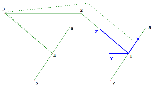
I put together a stick-figure FEA model over the past few days. Really the model is simple, but pulling the numbers in and out of the solver (and checking that I did it right) takes time. Interesting results.

The gantry is an inverted “U” which must resist moments when in operation. The legs of the “U” are supported by the linear guides. These require arms that stick out forward and back. There are points where load is applied at the motor(s). The arch is made with 4x4 square tubing, the end beams are 1/4" plate.

My FEA model asks what happens when the motors on either side of the gantry get out of sync with each other. Later I will look at cutting forces from the spindle on the gantry. Will need to add elements to represent the spindle when it cuts.

This is an ancient (1990’s!) stick-figure FEA package that is free but unsupported called GRAPE:

CNC FEA 1

Linear guides at Nodes 5,6,7,8 are constrained in Y and Z, free in X and all rotations.
The locked motor is at Node 4, preventing only X motion
The applied force is at Node 1. I used a “unit” force of 1 pound to “see what happens”.

The displacement (dotted frame) in the figure is an exaggerated scale. The deflection at Node 1 is 0.00048 inch (1/2 thousandth of an inch). To go 0.001" (1 thousandth of an inch) of skew, the asymmetric load would have to be 2.1 pounds.

Interestingly, and somewhat coincidentally, I am expecting that a 200-step stepper motor with a 5:1 gearbox and a 1.5" rack and pinion drive would advance 0.00075" per step, which is very similar to the skew from the 1 to 2 pound asymmetric load.

Not surprisingly, it takes A LOT OF material to make this kind of structure much stiffer. The 4" square structural tubing is pretty beefy as it is. It’s good to have some dimensions and resulting loads/deflections worked out from an example like this. To consider for a while in the back of one’s mind.

A little further into it.
Variations of structural tubing improve the stiffness, but only marginally. They also affect the weight that the motors must push around. Once I noticed the penalty from adding weight I got more strategic with my choices of structural tubing for the gantry frame. So doing the FEA made it possible to make it 100 pounds lighter!

I’m also making some progress with a “power budget”. Adding up the power required to start, move, accelerate, and cut… when all expressed in terms of motor power, it’s becoming possible to select a motor size for a desired performance.

The other budget is harder to face. Linear guides are expensive. Has anyone ever used aluminum guide rails with teflon runners? They cost half as much as the stainless kinds.
Example: McMaster-Carr 6109K52

Yes, they work ok for light duty. Not sure I’d trust them for this, the wear on the teflon might be pretty quick?