I’m looking at a project where the roof over the house is a gable type roof with hips at the ends. The residence is about 70’ long and 25’ feet wide. Currently the master bedroom, which is located in the front of the second story under the hip portion of the roof, has 9’ ceiling with ceiling rafters and collar ties, which are keeping the gable/hip from spreading. The homeowner/architect want to create a hip cathedral ceiling over the master bedroom. This is going to require removing the ceiling ties. The hip roof at one side of the roof will the same slope as the current roof, and at the other side of the room the slope will be different as there is a 3’ wide closet being built along the exterior wall. I’m wondering how to frame this out and still provide support for the roof to prevent the outward thrust. I can provide drawings if my explanation is not clear.
Thanks
@mfstructural Posting the drawings will be a big help. Sounds like there are no existing roof trusses, just rafters / collar ties… is that correct.
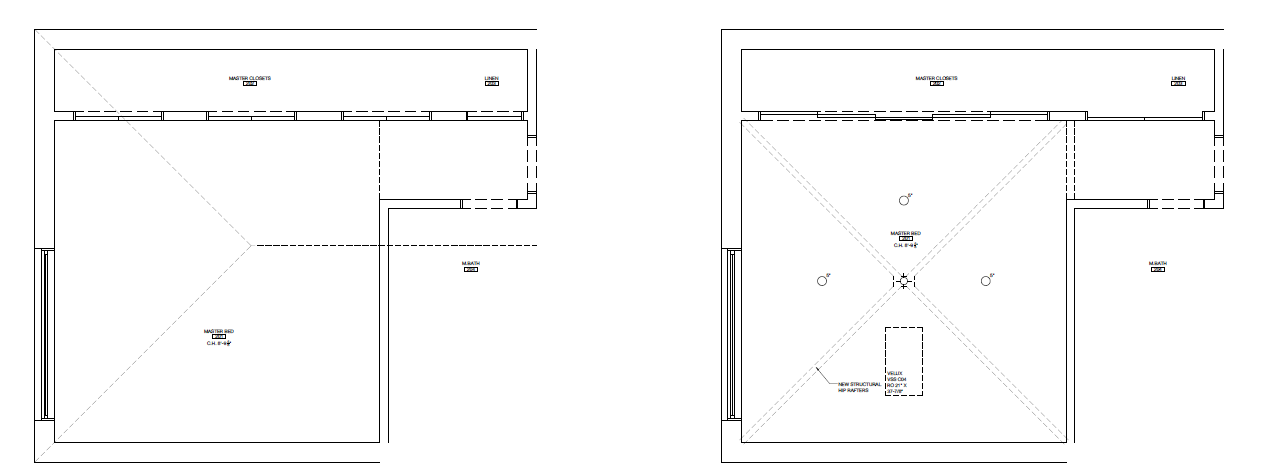
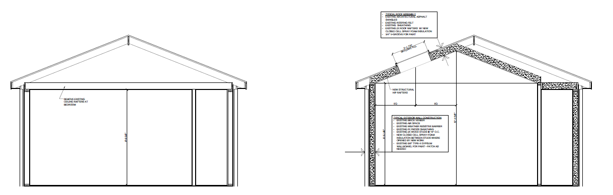
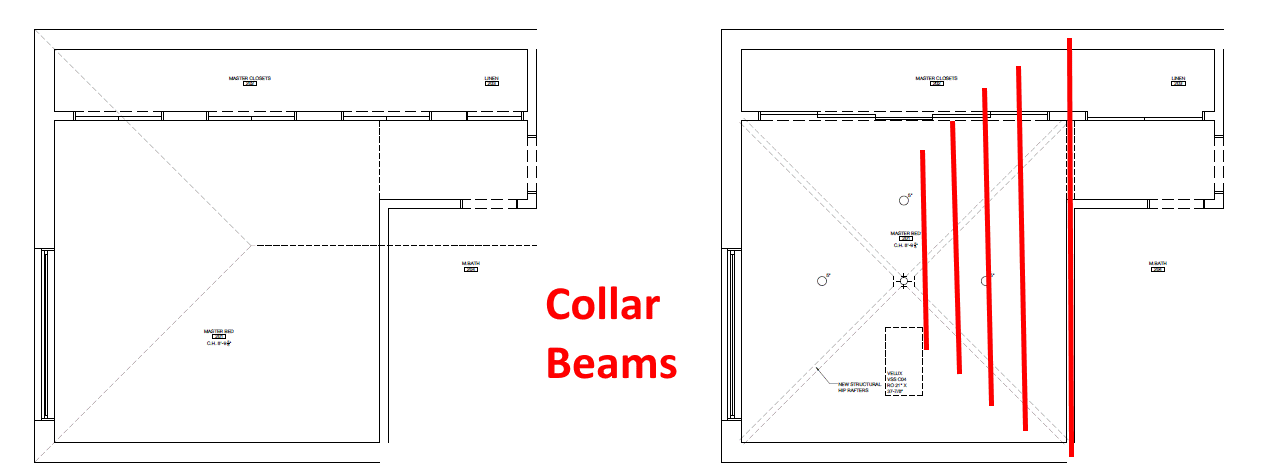
I included the images below. The plan/elevations on the left are the existing and on the right proposed. You can see the ridge and two hip rafters existing and the new hip roof in the bedroom, which uses one existing hip rafter and will require modifications to the rest of the framing. My concern is the outward thrust.
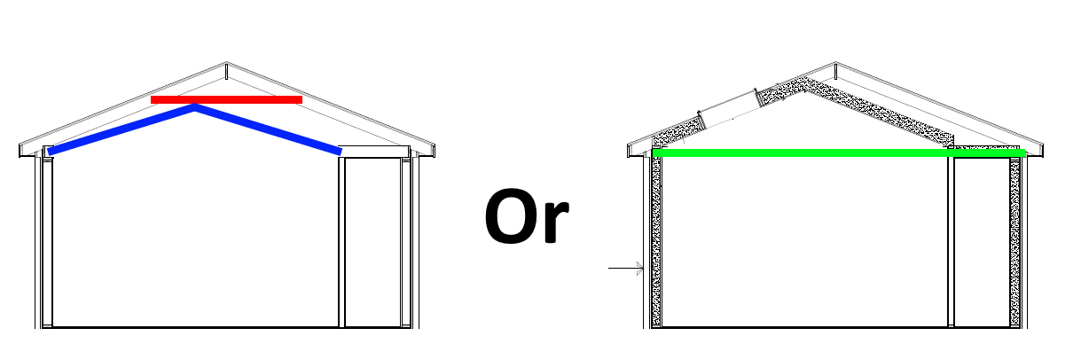
Two approaches come to mind, both of which are just concepts subject to as-built construction and analysis:
-
Replace the ceiling joists with collar beams (red) and add rafters (blue) up to the collar beams to create a shallower cathedral ceiling.
-
“Dress up” or replace the existing ceiling beams (green) so that they are architecturally exposed below the the cathedral ceiling.
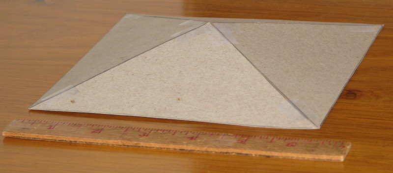
Taking a better look at the drawings, seems there is a pyramid master bedroom ceiling underneath the building’s hip roof. If this is so, it is said that pyramids have “magical power”… and they do when it comes to certain structural properties. A pyramid is self-bracing, i.e. the four walls supporting a pyramid do not need any additional restraint to resist outward thrust… there is no outward thrust when gravity load is applied.
To check this out, I modeled the pyramid ceiling… not a software model, a real 3D, analog cardboard pyramid, 6 inches on a side with at (typical) 4:12 slope. For something made of cardboard and tape, the model is both incredibly rigid and strong. As long as the pyramid remains intact, walls supporting it are not going anywhere under gravity loading.
Hey SlideRuleEra, sorry for the delay in responding…I tore my achilles and was dealing with that the last month…that’s a great analogy. I’ve been trying to wrap my head around that. Kept thinking that but that then depends on the strength of the connections at the peak, correct? When an analysis is performed, let’s say using RISA, you’ll get the vertical reaction at the top and bottom of each member. So as long as the connections of the ridge are adequate the hip should not deflect.
In this case though we are installing this hip roof under an existing gable roof…so the rafter/ceiling ties making up the ceiling and preventing outward thrust of the gable framed roof above the faux hip roof above the master bedroom are removed. So the hip is ok, but the gable is still going to want to push the walls out…that’s the issue.
One fact of the existing gable is going to serve as half the faux hip roof, but the opposite facet of the gable will have the hip framing below, as pictured in the drawing. I think this then means we still have outward thrust on the walls, no?
Sounds painful, hope your recovery is going well.
I believe when a pyramid is gravity loaded, the first connection failure between facets will occur at the base (the eaves of a pyramid roof), not the peak. I loaded my “model” to failure (with my fingers), connections (tape) at the base failed first, as expected.
The way I see it, the shared facet will be self-braced by the pyramid ceiling. This shared facet will then brace the roof slope on the other side, until the ceiling peak is reached. Moving past the ceiling peak, bracing of the other side’s roof slope will steadily decease, then disappear. Fortunately, collar beam of increasing length can be installed above the ceiling. See the marked up sketch.
What do you think? My engineering skills predate software. I do everything using old fashion ways… maybe you can check this with a software model. Engineering judgement tells me the pyramid’s self-bracing concept will make the solution easier than it looks. I would like to know what you find, this problem is a real challenge for my version of old fashion ways.
Looks like to me that a Tension-ring to support the hip structure is very viable here. The square is there - all you need is the corner connections from the wall top double plates to the hip developed, and the tension in the wall plates in between.
Easy Peasy!
Then you can do whatever you like with the ceiling look.
I think both solutions mentioned are viable. I racked my brain over this one for some reason. A pyramid structure is going to fail at the bases first, so the “tension ring” msquared is referring to would basically prevent outward thrust of the pyramid and failure. So you have to develop those connections, but then you have to check the walls for outward thrust, no? or since the top of the wall is “braced” by the connection to the roof you don’t have to worry about it.
Thanks