QUESTION
Can anybody tell me how I would determine the “K” value for a post fixed at its base and laterally supported at mid-height? The axial load is applied at the top of the post.
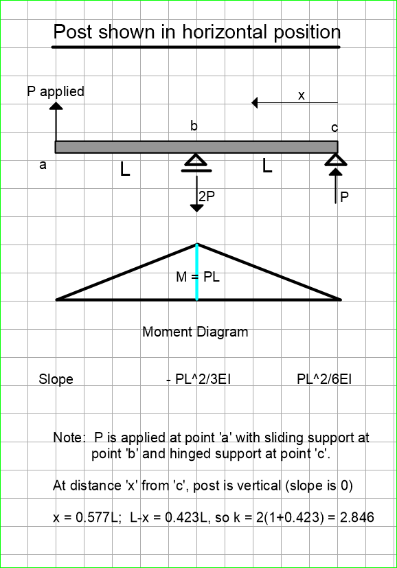
The top of the post is unbraced, (like a propped cantilever running vertically). The restraint at mid-height is only for lateral translation.
REPLIES
Tomfh
I used Microstran and ran a linear buckling analysis.
K=2.7 is for a pinned base. A rigid base gives K=2.5
These values make sense if you draw your buckled shape. The tip to crest distance will be approximately 1/2 of your effective length.
Off the top of my head, I would say that, for a pinned base, the answer should be 3.0 where L is the half length of the post. Should be a bit less for a fixed base, I would guess 4/3 *2 = 8/3 or 2.7.
I would say that the values given by Microstran are not only wrong, they are not conservative, at least by my calculations.
If the post is laterally supported at mid-height and pin supported at the base, it isn’t a mechanism. I am assuming that the mid-height restraint is capable of preventing the midpoint of the post from moving laterally.
Fixing the base, so far as I can see, does not change the k value very much. It forces a point of contraflexure in the post at L/3 from the bottom. It results in zero slope at a height of 2L/3, leaving the effective length of cantilever to be 4L/3. So the k value ends up as 2*4/3 or 8/3 or 2.67.
The calculated values of k are theoretical. It may be prudent to consider values of 3.0 and 2.8 for pinned and fixed base respectively.
@Dik,
I think I see the problem. My sketch indicates “Pinned in middle” which I believe is misleading and I’m going to change it when I have time. It’s not the post that is pinned in the middle…there is a pinned support at the middle of the post. The post is continuous. Thanks for pointing that out, Dik.
I just ran this problem through my Demo version of Strand7, using totally arbitrary properties. The buckling load with a fixed base was 1.153 times that for a pinned base.
With totally arbitrary properties, we don’t know the slenderness ratio of your selection. If it was close to 200, the maximum permitted by code, we could get a rough idea of how we compare.
For a HSS76x76x4.8, r = 28.8mm. My CISC handbook lists a Factored Axial Compressive Resistance of 67 and 58 kN for kL of 5200 and 5600 mm respectively. That would be a pretty slender column with an L/r of 180 and 194 for the column lengths listed.
The strength ratio is 67/58 = 1.155, very close to your value of 1.153.
The length ratio is 5600/5200 = 1.077, a little more than 2.846/2.667 = 1.0671, but close enough to confirm that we are in the ballpark.
Strand7’s Demo version has all the analysis capabilities of the full version, but has two important operational limitations: Severely limited problem size (with the limiting applied to the number of elements); and no ability to store a model. I have COMPLETELY forgotten what dimensions I pulled out of my RRRs for the analysis I performed. But because it was a linear buckling analysis I believe that the ratio I presented would apply regardless.
I don’t think so. The slenderness ratio affects the buckling relationship. But for very slender columns, we could turn to Euler’s formula where the critical buckling load is inversely proportional to the square of the length. On this basis, I would have a ratio of (2.846/2.667)^2 = 1.139 for FixedBase/PinnedBase strength as compared to your ratio of 1.153 or about 99% of your value. Close enough?
I created another Strand7 model. Two beam elements, each 1m long, supported X & Y at bottom, X at the node where the two beam elements joined eachother. Material was steel. Cross-section was a solid circle. I performed six analyses, as follows.
Diam=0.001m, base pinned, buckles at 0.0134N.
Diam=0.001m, base fixed, buckles at 0.0154N.
Diam=0.010m, base pinned, buckles at 1.34N.
Diam=0.010m, base fixed, buckles at 1.54N.
Diam=0.100m, base pinned, buckles at 134N.
Diam=0.100m, base fixed, buckles at 154N.
The constancy of the fixed/pinned ratio over such a large range of slendernesses was to be expected because the analysis was nothing more than a linear buckling analysis.
How did you determine that you had a wide range of slenderness? You have not provided the length of element in any of the six analyses. (My mistake…they all have a length of 1000mm). The slenderness ratio is defined as L/r where L is the length and r is the radius of gyration of the element.
If the slenderness ratio is constant, I would agree that your results are to be expected.
EDIT: I missed the fact that you gave the length of all samples as 1m. Wow!
So your maximum slenderness ratio KL/r was 2.85L/r, or 2.85L*4/D = 11,400/D (D in mm)
or 11400, 1140 and 114 for the three comparisons you ran. The first two are completely out of range, but the third one falls in acceptable range for a column. I’m surprised that you are finding a slenderness ratio of 114 to be governed by the same expression. If you went one step further and tested a bar of 1m diameter, what would be the result?
I wasn’t trying to design a column to a code. In all except my first post I was trying to prove a simple theoretical point regarding “linear buckling” analyses, by using numerical examples.
I’ll switch to formulae instead. A simple classic Euler column, each end restrained against transverse movement but not against rotation, will experience linear buckling at a load of 1pi²EI/L². Add rotational restraint to both ends and the linear buckling occurs at 4pi²EI/L².
The ratio of these two results is 4, totally independent of E, I & L.
Similarly, the RATIO for the OP’s configuration with and without rotational constraint at the base, will not depend on his E, I or L.
Yes, there is a misunderstanding between us. The OP wanted to know how to determine the “K” value for a post supported in a particular way. I had addressed that question when you advanced a fixed ratio of buckling load for base fixed versus base hinged.
You did not remember the slenderness ratio you had used in your Demo version of the Strand7 program, then declared your ratio would apply regardless of slenderness.
I stated I didn’t think that was true, recalling that inelastic buckling can occur for stockier columns. You went about demonstrating that Euler’s formula worked for three sizes, two of which were completely outside the range of anything we could possibly consider and one with a mid range slenderness.
Euler’s formula still works for inelastic buckling, but a reduced value of E must be used because the stress/strain curve is not linear at the critical buckling load. I don’t know how much difference it makes, probably not much but, contrary to your last sentence, the ratio of critical load with and without rotational constraint will depend on E if buckling is inelastic.
EDIT: The following scan and comments were added April 30, 2020.
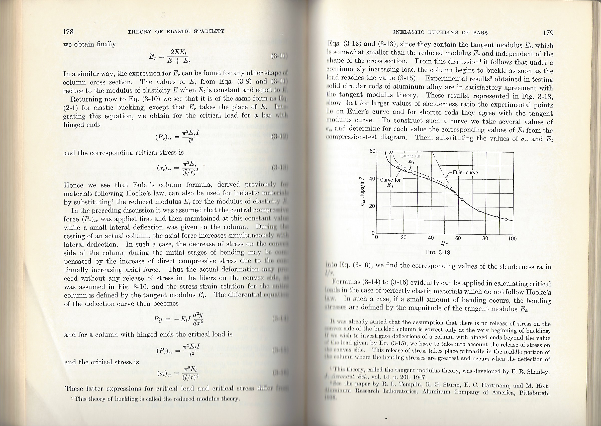
The following scan is taken from “Theory of Elastic Stability” by Timoshenko and Gere. Notice how the E value departs from the Euler curve for slenderness ratios between 0 and about 50. All of your examples had slenderness ratios in excess of 100.
As a matter of interest, why don’t you check an example which falls into the affected slenderness zone using Strand7. If you select a very stocky column, it is possible it will not buckle at all but will find a different mode of failure. You can see from Fig. 3-18 that for slenderness values below 6 or 7, the critical compressive stress exceeds 60 ksi.