Hello,
My team of students & I are currently working on a concept for a new type of dishwasher. The concept requires a system, which is able to pump high-pressure water through a large number of holes/nozzles, that are distributed equally over a plate.
Our issue regards how to distribute the water-flow equally across the nozzles.
The flow is vertical and pumped from the bottom - and it has to be sprinkled with high pressure. Is it possible to create a manifold with a slope edge, that ensures the pressure and therefore also amount of water/flow is equally distributed? If so, where can i find some theory explaining how to calculate the shape of the manifold?
If there is no flow, the pressure will be constant throughout the manifold (assuming the outlet surface is level).
As soon as water starts to flow through the manifold, the pressure will reduce the further you get from the inlet. Tinkering with the shape of the manifold may change the shape of the pressure distribution but it won’t stop it falling as you get further away from the inlet.
Two things you can try: First is to make the cross-section of the manifold large relative to the total area of all the nozzles to bring you closer to the no-flow case. The other is to design the manifold with multiple inlets so there’s less difference in the distance between nozzles and their closest inlet.
Have you decided how you’re going to deal with entrained particulates? The flow through the nozzles will stop being identical the moment one of them gets blocked - and a flat manifold with many holes sounds like a real pain to clean.
You may be overthinking this.
Some questions:
What is the minimum pressure that you need at the nozzles?
What is the maximum pressure that you can accept?
What is the pressure that you want your pump to develop?
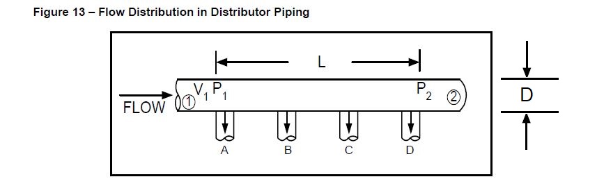
Equal pressures and pressure drops:
If the manifold cross section is large in relation to the cross sections of the nozzles the pressure difference between nozzles will be negligible.
@Latexman, I had a question similar to that of Jens and your reply was very helpful. Where did you find the plot above? A textbook? I’ve tried searching but haven’t had any luck. I’d be interesting in reading further on the topic and specifically how these curves were obtained.
@mechman , It’s from an old “Fluid Flow Manual” from one of my previous employers, so not in any textbook I know of. It may have originated in someone’s PhD thesis, but I’m guessing.