SOURCE
https://www.eng-tips.com/viewthread.cfm?qid=467266
The above URL contains the entire discussion. Below is a snippet.
QUESTION
I am really stuck with the design of a 350 mm thick flat slab (no column drops). The structure is a podium supporting five floors above. As the structure has an irregular column layout, line loads and point loads located in random areas I intend to design it with FEM. I previously did some design of a flat slab but with a regular column layout using FEM. I then used the column/middle panel strip method to average peak moments over the columns so I could specify the reinforcement. In this case however I just don’t know how to apply the strip method due to the irregularity of the column layout as I don’t know how to define a panel width. Maybe you guys know some other method?
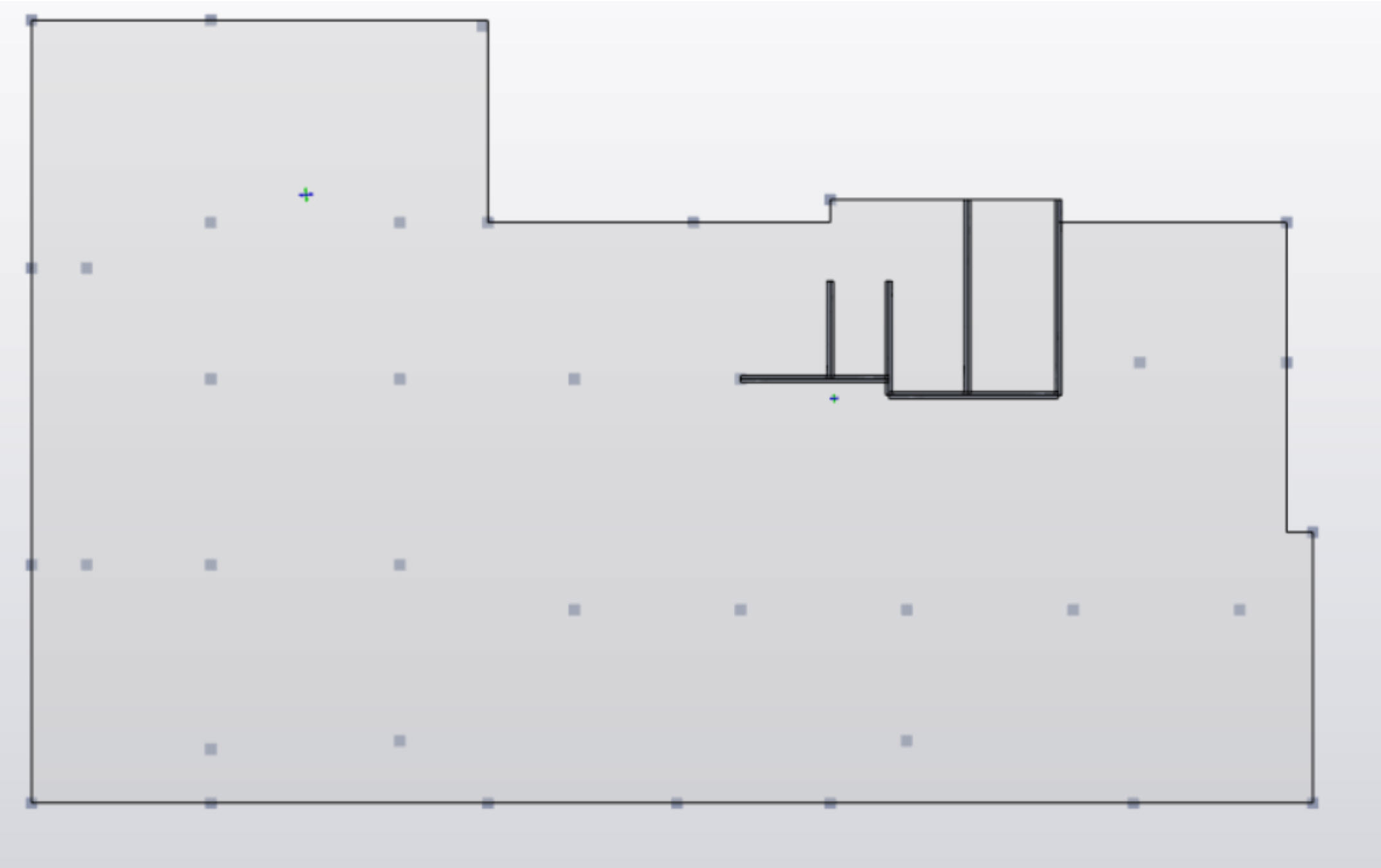
By the way I am using Tekla Structural Designer software and below there is a plan view of the podium.
REPLIES
JoshPlumSE
Below is something that I wrote up during the development of RISAFoundation for users that ran into similar questions about what the widths of their strips should be:
Setting the Width of Design Strips
One of the most important design considerations is how wide to set the Design Strip. If the width is set too large, then the program will average out the moments and shears over too wide of a region. This would result in unconservative design moments and shears. Similarly, if the strip is set too small, then the effect of stress risers in the FEM analysis will be over estimated and the design will be over conservative.
The setting of the design strip widths is truly a matter of engineering judgment. RISA Tech, Inc. makes no endorsement on what methods would be most appropriate.
ACI Definition of Strips (ACI 318-14 Section 8.4.1/ACI 318-11 Section 13.2)
This section of the ACI code is really intended for elevated slabs. But, the concepts can be extended into mat foundations as well. The requirement for “column strips” is that the width on each side should be set to 25% of the span length or width whichever is smaller. Then the “middle strip” is defined to span between the edges of the column strips.
This method requires engineering judgment for column grids that are not perfectly aligned and rectangular. In addition, when the column strip becomes very small then the middle strip may become very wide so that the entire slab is included in either a column strip or a middle strip.
The ACI strip method listed above is based on essentially 1/2 of the mid-span tributary lines. The hand calculation methods would have you design for the full tributary moments over this smaller width which should be conservative. Computer methods (like RISAFoundation) will design for the average moment over the assumed design width which should result in a more efficient design.
Zero Shear Transfer Method
The Zero Shear Transfer method used the shear force contours perpendicular to the span of the slab to set the design width. This should provide a result very similar to using the mid-span tributary lines, but is a bit more theoretically derived for non-rectangular column layouts. This method is described in greater detail in the PTI publication Design Fundamentals of Post-Tensioned Concrete Floors. Ideally, this method should give design strips of similar width to the ACI strip method. However, it is more rationally derived and should work better for cases where uneven column spacing makes the strip method difficult to apply.
Zero Moment Method
In a similar fashion to the zero shear transfer method, the Zero Moment method uses the moment contours to identify where the moment changes sign. This can be used to set the design strip width approximately equal to the distance between zero moments.
Shear Perimeter Method
Another basis would be to set the design width equal to the pedestal width plus a distance ‘d’ or ‘d/2’ on each side. This will end up being a more conservative assumption for flexure than the other methods listed. As such, it would be more appropriate for situations where shear or punching shear failures are a primary concern. Examples would also include cases where the pedestal is very large such as for a vertical vessel or grain silo. This is similar, though not identical, to a method given in the NEHRP document GCR 12-917-22 (Seismic Design of Reinforced Concrete Mat Foundations).
Hybrid Method / Engineering Judgment
A variation on these methods would be to start off setting the column strip using the ACI strip method. Then, if necessary, the width could be modified based on considering the other methods. This is especially true for situations where the column grid is not aligned or rectangular.
In addition, when the middle strip widths get too large, they could be set to values closer to the column strip width. The middle strip would normally be centered on the area with the highest mid-span moments. This would neglect lower moment regions between the column and middle strips. Hence the strips would designed for a higher moment per unit width. This reinforcement could then be extended into the lower moment regions between strips. Or the user could set up another design strip for these lower moment regions.