QUESTION
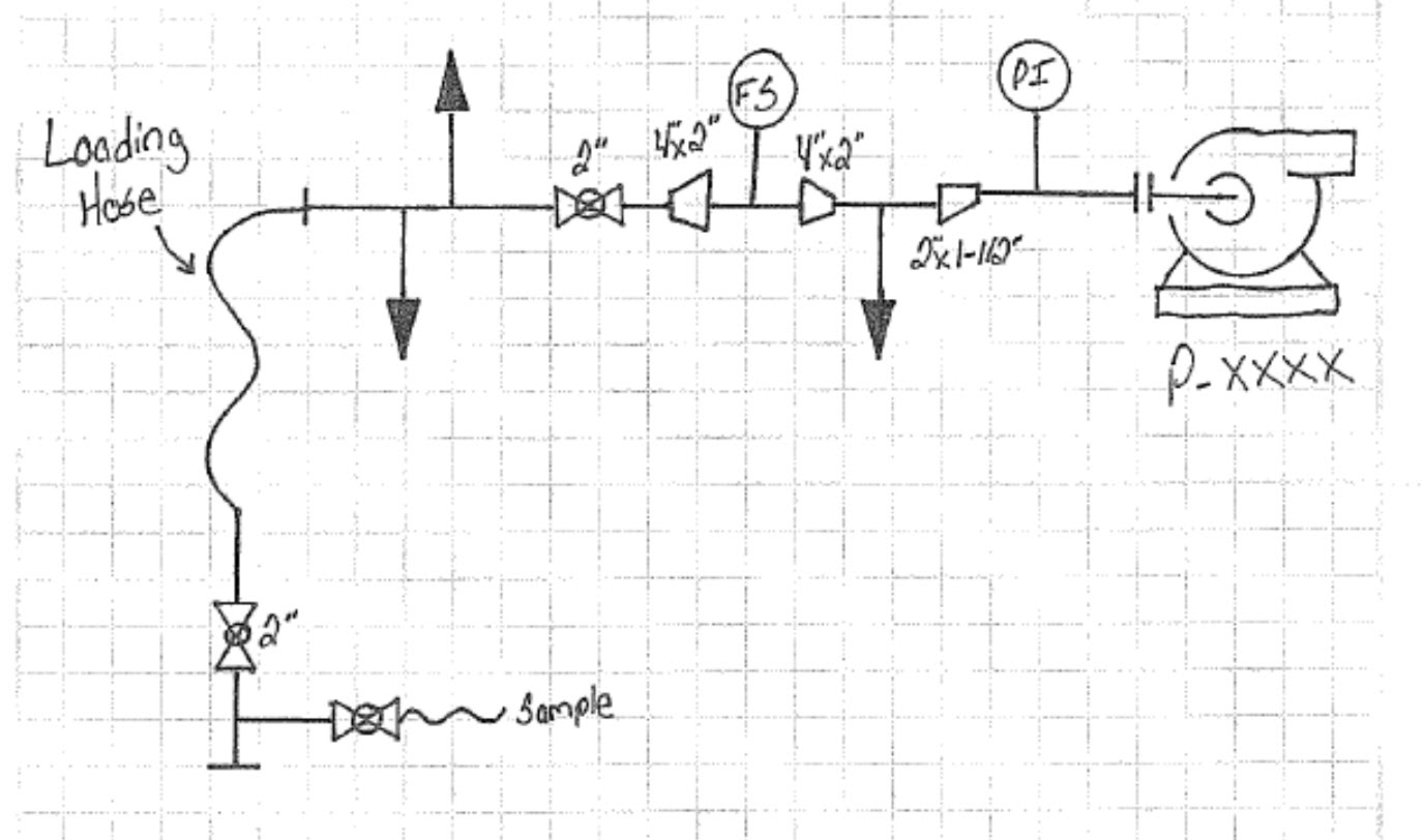
Process and E&I are developing P&IDs for an upcoming project. The picture below shows the preliminary drawing they have come up with. As I’m sure we all know by now, concentric reducers should not be used in pump suction lines unless the pump is a top suction pump, which this one is not. I’ve brought this point up to them along with discussing cavitation, but as of now they are not wanting to change what they have come up with. Their reasoning being the line size is too small for the flow switch insertion into the pipe and they want the flow switch to protect the pump (obviously).
Before I go back and argue some more, I was looking for some reinforcement that I should continue this argument and look for an alternative solution.
The pump will be used for offloading tanker trucks with refinery grade propane and sending it off to bullet storage tanks.
REPLIES @KoachCSR
I believe you are justified in continuing the argument - from what I see, there’s a possibility in vapor accumulating in the segment containing the flow switch. Unless there is some nuance with pumping liquid propane that I am not aware of, I agree with your position as stated.
Snippet source https://www.eng-tips.com/viewthread.cfm?qid=427521
What is the elevation difference between the tanker truck min liquid propane level and the pump suction? What type of isolation valves are specified? Ball valves preferred over globes or gates.
Is there a way to fill the line, vent off air, prior to starting pump? Has possibility of initial pump start causing FS to trip (2 phase flow) been considered?
Note: Many years ago, I dealt with a nightmare sample pumping system in a nuke plant. The low pressure water source was approx 18’ below pump suction, piping was 3/4", flow was ~25 gpm. Isolation valves including suction line were 3/4" globes. At rated flow, pump was in cavitation and flow would drop to zero.
Our solution, which was the least cost, was to change the suction line globe valve to a gate design. It didn’t fix the poor system design, but it corrected the cavitation issue.
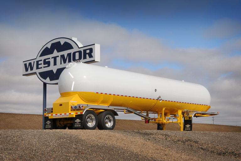
Most propane transport trucks would have about 3’ between the tanker truck min liquid propane level and the pump suction if grade is level:
The tires are about 3’ tall. The belly of the tank is about 1’ above the tires. The pump baseplate plus suction nozzle is about 1’ above grade. So, about 3’. The dimensions of each installation should be verified.
The valve symbology indicates ball valve.
Not sure, but a time delay in the first minute of running the FS logic may filter out start-up transients. This could be fine tuned during commissioning.
Yes, 25 gpm in a 3/4” line feels too small for a suction line.
For this case, please send the control circuit for the flow switch with pump in automatic mode to check it.
I think that you will have high level switch used for storage tank high level to switch off the pump in automatic mode.