QUESTION
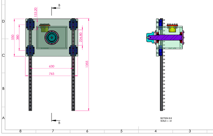
I am developing a lifting mechanism for which I need to know the linear guide selection procedure along with the load calculations
REPLIES
MikeHalloran
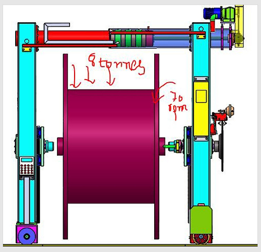
Your mechanism appears to be a pair of columns, each fitted with a cantilevered shaft that rises under power. The shaft ends are stubs that fit into a reel carrying 6 tonnes of something, that is unwound passively at up to 70 ipm or fpm for ?pm.
The stubs engage the reels by means of a mechanism that may be mechanical or hydraulic the moves the columns toward or away from each other.
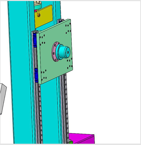
The linear guides carry the bending moment from the cantilevered shafts holding the reel ends, plus whatever loads might accrue from misalignment of the columns from their drawn position.
Is that about right?
Comments:
- The tension brake looks a bit small for continuous duty, but ~ok if it’s a lock/park brake.
- It will need a guard to protect personnel from contact or burns.
- I hope there is some mechanism or structure, not shown, keeping the columns in good alignment.
- If only the span adjusting mechanism carries the moments between them, it may have severe stiction problems, and the allowed misalignment and resulting moments will severely tax the linear guides.
- Any equations you develop for guide selection must include misalignment, which basically means it has to include the stiffness of the entire combined hoist structure.
Opinions:
All of the roll handling equipment, which this basically is, that I have ever seen does not include linear guides or sliding ways or any such friction- susceptible component.
Most of them comprised frames cut from very sturdy plate connected with very sturdy tie-bars or shafts, and accomplished movement by means of rotation, not translation.
Hinges were typically easily replaceable mounted bearings bolted to frames, or replaceable bushings inserted in bushing holders welded to plates, or some similar arrangement that could be repaired in minutes.
SOURCE
https://www.eng-tips.com/viewthread.cfm?qid=438443
Above is a snippet.


