Magnetic Circuits in Generators and Motors

Any motor designers out there?

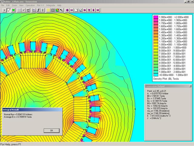
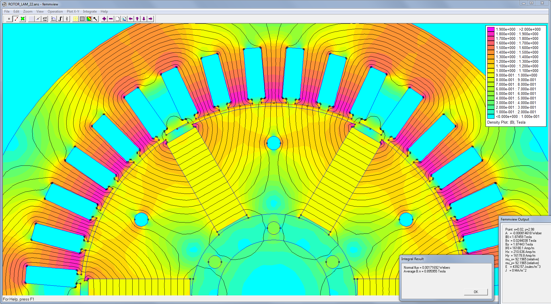
For many years I have been converting 3-phase induction motors into 3-phase self-excited generators by removing part of the rotor’s induction bars and replacing them with neo magnets. I’ve written extensively on the subject from a hobbyist perspective. Here in particular: http://www.sparweb.ca/3_Gen_MoCo/Baldy.html

I’ve done 4 of these conversions now, and I’m considering another, if a certain person I know commits to buying a custom wind-turbine from me.

Although I’m satisfied with the result - really have no reason to complain - I am interested in doing better. Neo magnets are expensive for one thing. The conversion is time consuming, and contains a lot of trial-and-error. There’s a point where I just throw a dart and hope for the best.

Are there any members that have a grasp of the details in designing the flux path in a motor with permanent magnets? Of course, there are lessons from the induction motor to be applied to this type of conversion, so I don’t want anyone to feel I’m not open to ideas or discussion. If you have heavy thick textbooks, all the better. If you did your doctoral dissertation on the subject, please pile it on, the more ODE’s the better.

This isn’t the first time I’ve posted on a discussion group about this subject. In the past I’ve encountered some confusion about what I’m trying to do, or advice to do things that are much more complicated that what I actually do, and have nothing to do with building what is, essentially, a BLDC motor/generator. I hope to stay away from those diversions but I do admit, what I’m doing is unorthodox. Hopefully you can trust me when I say that what I’ve built can contend with the best wind turbines that the NREL has ever tested, and that my goal is to understand why, and maybe do better. If that trust is hard-earned, I have written a lot on my personal journal site www.sparweb.ca and a forum dedicated to DIY renewables projects https://www.fieldlines.com/index.php/topic,149797 so maybe more reading there will help.

The alternative to these motor-conversions is, of course, to find nearly brand-new BLDC or similar generators in TEFC enclosures with fat bearings, 30Amp or more current rating and a linear V-N curve that can arrive on my back porch for less than 1000 US dollars. If you can find that (I’ve looked; it’s all trash) then of course this whole discussion is moot.

@MagMike, can you help here?

SparWeb,
I’ve kept tabs on your work over the years and have been mightily impressed. I have to admit I can only offer limited assistance. New motor/generator designs are incredibly complex, so many design requirements, so many tradeoffs…
The best advice I can give would relate to the permanent magnets in the design. NdFeB magnets are very powerful and one can put too much into a motor/generator design. The laminations can only carry so much magnetic flux before getting saturated. Anything more is wasted and can actually degrade performance by creating drag or other forms of interference.
I’d be happy to run simplified/straightforward type analyses in FEMM to evaluate potential saturation.

One thing that I have come to realize after a number of conversations with you, Spar, is that optimization is not as important as I thought that it may be for a small conversion.
The electrical output is limited by the mechanical input.
If the flux is less than optimum, this may be compensated by other means.
One means is changing from a star connection to a delta connection to get the same power from a lower voltage.
This is an example, there are a number of other ways.

Thanks for the offer. I’ve used FEMM extensively myself, but with limited background in the field (sorry no pun intended), maybe your offer is a kindly polite way to tell me the models I put on my website are bunk!

There are two goals competing for attention, here.

  1. learning stuff
  2. building good stuff

At times I’m just out to collect more information for its own sake. At other times I am keen to put it to use. That includes testing the result - often more fun than the build to me.

Here is a little more discussion on the topic you may not have seen: https://www.fieldlines.com/index.php/topic,150022

Absolutely. But most of these mysteries went away after I did the performance tests both on the bench and in the air.

Are you absolutely sure that a small amount of saturation isn’t beneficial? The field intensity in any structure containing iron and magnets is never completely uniform. Corners and edges get over-saturated, but the total flux would still go up if the field increased a little more, regardless of the depth of saturation in a few small areas.

The Baldor conversion’s FEMM model showed several points of deep saturation but they were tiny compared to the area of the pole with flux to be linked.

Baldor_FEMM_12flats

I’m not sure,Spar but I think that saturation in a generator means;
“That all she is and there ain’t no more”.
When a motor goes into saturation, the back EMF stays about the same but any increased voltage is limited by the air core induction of the windings, not the iron core induction.
As a result the current increases drastically.
In a generator, saturation limits the induce voltage and all that happens is the voltage does not increase further.
I was thinking about a different design that you showed me that some of the build it yourself guys were using. It may have been possible to increase the flux density, but everyone was happy with the results as it was built.

I’ve been intrigued by unipolar generators.
On drawback is the low voltage and high current.
Add to that the use of brushes to extract the current .
High current, low voltage and brushes are not a good combination.
How about if we held the disk stationary and spun the magnet in a circle near the edge of the disk?
However we move the disk and the magnet relative to each other, are there eddy currents induced in the disk causing losses?
Can we reduce the eddy currents by slotting the disk something like the daisy wheel in old printers?
Do we need the full disk if we are keeping it stationary or do we only need the portion beneath the magnet path?
Comments suggestions.
I have a thought as to how to gang a number of disks in series to increase the voltage without brushes.

Regarding saturation, there is no exciting current to worry about in a PM generator. At first glance, I don’t think saturation would be a problem except that you are wasting space with bigger magnets than you need with not very much benefit in return.

Hi Bill,
I don’t know the meaning of the term “unipolar” motor, but it doesn’t match what you describing below.
If you’re talking about an axial-flux generator, also known as an Axial-Flux Alternator (PMA) well, I wrote a white-paper on that subject about 15 years ago after building a few myself:

My white-paper proved to be popular and it’s been translated into a few other languages and copied (without asking permission or giving credit, but I’m not bitter!) many times since.

Since then I have gotten away from building those because they are nowhere near robust enough for a long-lived wind turbine, although they can have higher performance than the generators I have built from motor-conversions.

Regarding brushes in generators, a reality check is in order. Brushes wear out after a few thousand hours or a few million revolutions, whichever happens first. On an engine-driven DC generator, that will go a few years. On a wind turbine, that’s only a few months.

Hi Pete,
I’m hoping for a textbook or some technical report references that I can read for a deep dive into the subject, if you have them.

I have difficulty relating the advice you’re giving to my practical experience. The model in the FEMM drawing above is a model of what I built, and it performed as predicted by the analysis.

I posted the cross-section from a FEMM simulation hoping you or anyone else could refer to it, if talking about saturation. There are surely many points of saturation, but if you look carefully, also several teeth with less than 50% of the flux density they can carry. So adding magnets can be shown to increase the flux in the gap by “filling in” the empty spaces. Absolutely it is not efficient. But that’s not really the point, there.

I am looking for ways to deliver a more uniform field across the gap of each pole. This design isn’t ideal and you really don’t need to explain why it’s not ideal - I get it. The point was to fabricate a generator with inexpensive materials with common machine shop tools.

This and other limitations affect what I’m building, but I’m not daunted. I enjoy the challenge. The ceiling above me is a lack of ANALYTICAL DEPTH because I can’t find one single book on the subject of electrical motor design that actually covers these design details. I’m not expecting you guys to know this yourselves, just hoping you know where to look.

Years ago while I was writing my PMA white-paper, I had very little difficulty extracting enough info from my college physics textbooks, and a few keen observers on the internet, to build enough understanding of the axial-flux alternator to make accurate FEMM and analytical models (Mathcad) that made good predictions when tested against the generators I built.

For my motor-conversion projects, I have still made more FEMM and Mathcad models, but they are much more empirical. For some reason, this is much much more difficult to analyze, and a complete mystery to everyone I ask about it.

I’m just asking you to name a book, if you know of one.

Hi Spar.
I have been thinking a lot about your saturation and the implications, based on first principles.
I’m still cogitating.
It takes a lot longer than it used to. grin
The more that I think about the unipolar motor, the more I think that it is a bad idea.
Yes it works, BUT.
An eddy current brake works better.
Visualize a basic demonstration eddy current disk.
An aluminum disk spinning.
As a magnet is brought near the disk, eddy currents are generated in the disk and energy is dissipated as IR losses of the eddy currents.
As the magnet is brought closer to the spinning disk, the eddy currents increase and the braking torque is increased.
Now let’s look at the construction of a unipolar motor.
The demonstration eddy current brake may be converted into a unipolar generator by adding a brush to the rim and a brush to the shaft.
Have we eliminated the eddy currents and the associated losses?
No, we have diverted some of the eddy current and moved the associated losses away from the disk.
Due to the very low resistance of the disk, we can harvest only a small part of the eddy currents.
Do unipolar generators and motors work? yes.
Do they have a use?
Yes, they can demonstrate the presence of eddy currents and estimate the EMF causing those currents and they may be used to demonstrate that the effect is reversible.
By the way, I have, somewhere a text on Electricity and Magnetism that may be useful to you.
I’ll find it eventually.
You know that I’m not that fast anymore. grin
In your paper, I wondered about the mismatch between magnets and coils.
In all commercial, AC machines, the magnetic poles are matched to the number of poles.
Is there an advantage to the mismatch when the output is rectified to DC?
What am I missing.

Yes, I’ve built that once. Had lots of fun experimenting with it. Driven on a lathe (5 HP) I could apply enough braking load to significantly slow it down. Everything got hot very quickly and I had to stop.

What is that?
All I can find…


What are they for? Anything bigger than a cassette player?
Did you mention they have brushes? I hope to steer clear of those.

But my ears did perk up at the mention of an E&M textbook!


One brush is on the circumference and the other contact is the axle support.
I have to believe that they are tapping some of the eddy current.
Take the brush away and you have an eddy current brake.
I strongly suspect that many of the designs that come up with Google Images have never been built.
Spinning that magnet in place will do nothing.
Holding the disc stationary and moving the magnet in a circular path around the disk will give you the relative motion needed to generate a current.

Cutting the lines of force is a bit of a misnomer.
the conductor must move in the magnetic field in such a way that the flux intensity is changing, either increasing or decreasing.
Moving a conductor in a magnetic field in such a direction that the field strength remains constant will not generate.
Homopolar motors?
Google Images for homopolar motors and over 90% of the hits are powered by a AA cell.
A great demonstration, but not much else.
I once was responsible for about ten brushed machines.
A couple of hours every weekend was dedicated to doctoring brushes.
Slip ring are much better.
The slip ring brushes in an automobile alternator last for years.
(I admit, not much current.)
I’m going to take a look for that book on my way to bed.
Goodnight all.

@Bill, I may have said this already…
You would be a big hit on Fieldlines.com. There are plenty of folks there that love to self-teach with gadgets like that.

Anyway, as far as where I’m going with motor re-builds and conversions, more complex machines is where I want to go.

This is the next conversion project I’m considering:

Here what you see are the magnets not resting on the surface, but inserted in slots between wedge-shaped iron poles. The flux is much more evenly distributed in the teeth than the other method. I am hoping for this to be relatively simple to fabricate, but there are some details that concern me, such as the tremendous forces that develop during assembly. I will need support fixtures that may become quite complicate - reducing the simplicity of this approach.

Doing all of this with simulations like FEMM is great, but I really don’t have much math to guide my decisions. It’s mostly trial-and-error. The reason I keep imploring the readers for books of any kind on electromechanical theory or modeling, is that I want more insight into this design.

Some thoughts on saturation of the teeth.
I will go through the steps and conclusions that I have developed and rejected.
I. Saturation means that your magnets are strong enough. No need to worry about more optimization.
2. Wait, current is induced only when the flux density is changing. At saturation the change is so little that it may be disregarded. Hence, no change in flux means no current induced.
3. Third thoughts. what matters is the total flux cutting a coil, unless the entire flux path is saturated, the flux may still be changing.
4. Hold on, this is a generator, not a transformer.
There is still relative motion between the magnetic field and the coils.
It is the motion of the magnetic field rather than the change in magnetizing force such as seen in a transformer.
Saturation is serious in a motor, but it may not be as serious in a generator.
In your graphic, does the colour indicate saturation or just a high level of flux?
(Still thinking about saturation. Still subject to change.)

My old mind is slowly remembering experiences and drawing parallels.
In regards to an unchanging magnetic field.
In a transformer this may be caused by saturation but is more commonly caused by hysteresis.
The first time I saw this was on an unloaded wye/wye transformer bank.
The voltage reading taken with an analogue voltmeter was obviously in error.
(For the younger crowd, a typical analogue meter measures the average value and uses a “Form Factor” to scale that value to RMS. The form factor depends on the wave form.)
I suspected a distorted wave form.
The second time I saw this, I had a scope available and was able to confirm a distorted wave form.
With either hysteresis or saturation resulting in a short period of unchanging magnetic field strength, you will get distortion.
Imagine the positive half of a sine wave.
This rises to a peak and drops to zero.
With a constant flux, the EMF will be zero for a few milli-seconds and then the negative half cycle will commence.
When the negative cycle reaches zero, there will be another short period of zero EMF.
What does this mean?

  1. An analogue meter will not agree with a true RMS meter.
  2. In the case of a wye/wye transformer, comparing the line to line reading with the line to neutral reading, taken with an analogue meter, the ratio will not be the expected 1.73:1
    The ratio will be far enough off to be recognizable as “Something not right here”.
  3. Harmonics will be generated.
    Harmonics may be harmful, or they may not even be noticed, but it is well to be aware of the possibility.
    For a generator, it may be well to try to avoid total saturation.
    It may be well to try to make the transition from the north pole to the south pole as smooth as possible.
    But, still thinking.
    That’s the thing about predicting performance from first principles;
    You keep running it over in your head looking for factors and effects that you may have missed.

Well now we’re really going down the rabbit hole…
Yes, I see exactly that on my oscilloscope. This was a problem with more than just noise and efficiency as a consequence. It also made it impossible to measure RPM of the turbine with typical pulse-counter circuits. Multiple zero-crossings and variable waveforms depending on current load. Even the common tachometer chip LM2917 was confused. It took a very long time for me to stumble on a circuit with a fairly complicated architecture (including the software) to read a correct RPM.

A suggestion;
Try running simulations with weaker magnet strength and the same width magnet gap.
Try running simulations with a narrower magnet gap and the same magnet strength…