That was my thought too, zeus; the only thing I can think of (in our case) is that the female thread is a blind cavity, and it probably fills with water over time, so there may be resistance to advancing threads…slight, but some.
And…we are way off on a tangent for Spar’s tachometer thread…shoulda posted this as a stand-alone thread perhaps. Shrug.
Somewhat back on topic - the idea of a flowchart for an interrupt-driven program has been rattling around in my head, not sure if you care to see what I’m thinking, Spar, or if it would be worthwhile to you at this point?
Absolutely, I would love to see what you think would work in a flow-chart.
I really don’t use them much, maybe I should, but I come up blank when I try for this device.
Do you have tools to build flowcharts? I haven’t investigated that subject, either.
I mean, aside from just drawing shapes and putting text in them. Is there anything that works at a more nuanced level that tracks the data you enter, makes them make sense?
Dunno about software, beyond simple 2d CAD/drawing programs. I’ll try and sketch up what I was thinking in the next day or two, and scan it and post it here.
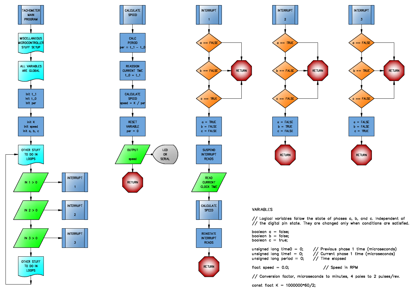
Ok here is a pdf of what I was thinking - was going to post a sketch, but I kept making mistakes…it was easier to lay it out in a Word document with shapes and lines and clicky grid points. tach flowchart.pdf (21.4 KB)
Holy smoke! All of a sudden there’s a flowchart.
OK, that’s capturing the logic and includes the variables that flag the state of the system at any given point. I think one of the steps that set the flags needs to reset Flag1 to “0”, but details aside I get the concept.
My previous reluctance to try this came from not knowing where to show the inputs that trigger the interrupts. Maybe simplest to just ignore it and move on to the logical expressions. But I feel like this doesn’t represent the way the program operates unless it has its 3 separate inputs. If a flowchart is supposed show inputs, where to they go? I think I can show a separate process in its own loop, that includes a “check for interrupt” and “goto” that would answer.
Different program codes read the internal clock time differently, so at least that can can be simplified to the just the basics.
Yeah, I think I made a mistake or two…but the flow, showing a continuous loop, I think captures the gist of what your algorithm does?
Regarding inputs…dunno. Flowcharting just shows a process, and has to be translated to specific processors. The flowchart I show could just be looped conditionals, checked sequentially as shown, or driven by an interupt-service processor like you use, or possibly by a state machine of fixed logic flip-flops like waross described (though how do you get the timer in a state machine, I guess it is just a parallel process that gets stopped/reset but dunno how you would do that with relays…)
Many years ago, when I spoke Boolean, there was an encoder system with some similarities to part of your system.
The system is probably still in use.
The encoder had two detectors, optical, magnetic, or other.
One target extended from the 12 o-clock position to the 6 o-clock position The second target extended from the 6 o-clock position to the 9 o-clock position.
The first signal enabled either the up register or the down register. The second signal entered one count into the selected register.
The segment from the 9 o-clock position to the 12 o-clock position reset the system for the next count.
The register contents could be used for either frequency or counting.
I see the unique part of your development as an ability to work over a wide range of frequency and amplitude and to reject noise on the signals.
Well done Spar.
I’m going to see if I can add this flow-chart as an appendix to my paper submission. It may be too late, but maybe it doesn’t hurt to ask.
Hello, Some trusted colleagues of mine have strongly encouraged me to include a flowchart with this journal paper submission. I have attempted to summarize the operation of the tachometer program as an aid to the understanding of the program flow and action of the interrupts. Please advise if this can be added to the article as an appendix. Thank you Steven
Hi Bill,
I’m having a bit of fun, and it seems like you have noticed. My answers to the respondents on the “other” forum are a bit coy at the moment. I have used them as “guinea pigs” to test my ideas without giving the whole method away. I admit it is a disingenuous thing to do, but it also sharpened a lot of my thinking as I was writing my paper. I plan to give them credit when/if my paper is published.
I received a response from IEEE that they won’t accept any late changes to my paper. They still haven’t reviewed it, yet.
No, I didn’t. It was rejected on (what sounded to me) pretty shaky grounds, but I didn’t have time any more to do a rewrite to their request.
On my part, I realized only after submitting that the section of IEEE actually has 2 instrumentation journals. I should have subb’d to the other journal. The other one is much more expensive to submit to, however. Since this isn’t worth a thousand dollars to me, I gave up.
Last point, these journals print mostly papers from kids getting their masters. I don’t think there is a quota, but usually space is limited. So I don’t need to make it any harder for them to get space.
Last point (for real) I started reading these journals when I started trying to publish. Most stuff in them is dross. I bet none of you EE’s would read most of it. The IEEE Spectrum is excellent. But instrumentation is pretty bland.
I need to revisit my tachometer.
I have started converting my wind turbine to operate on a 48VDC system, rather than the 24VDC that it’s been up until now.
This made me want to make changes to the data logger I built many years ago. Unfortunately, I’ve made so many changes, tweaks, additions, and replacements, that it’s hard to figure out how to change something as fundamental as its power supply.
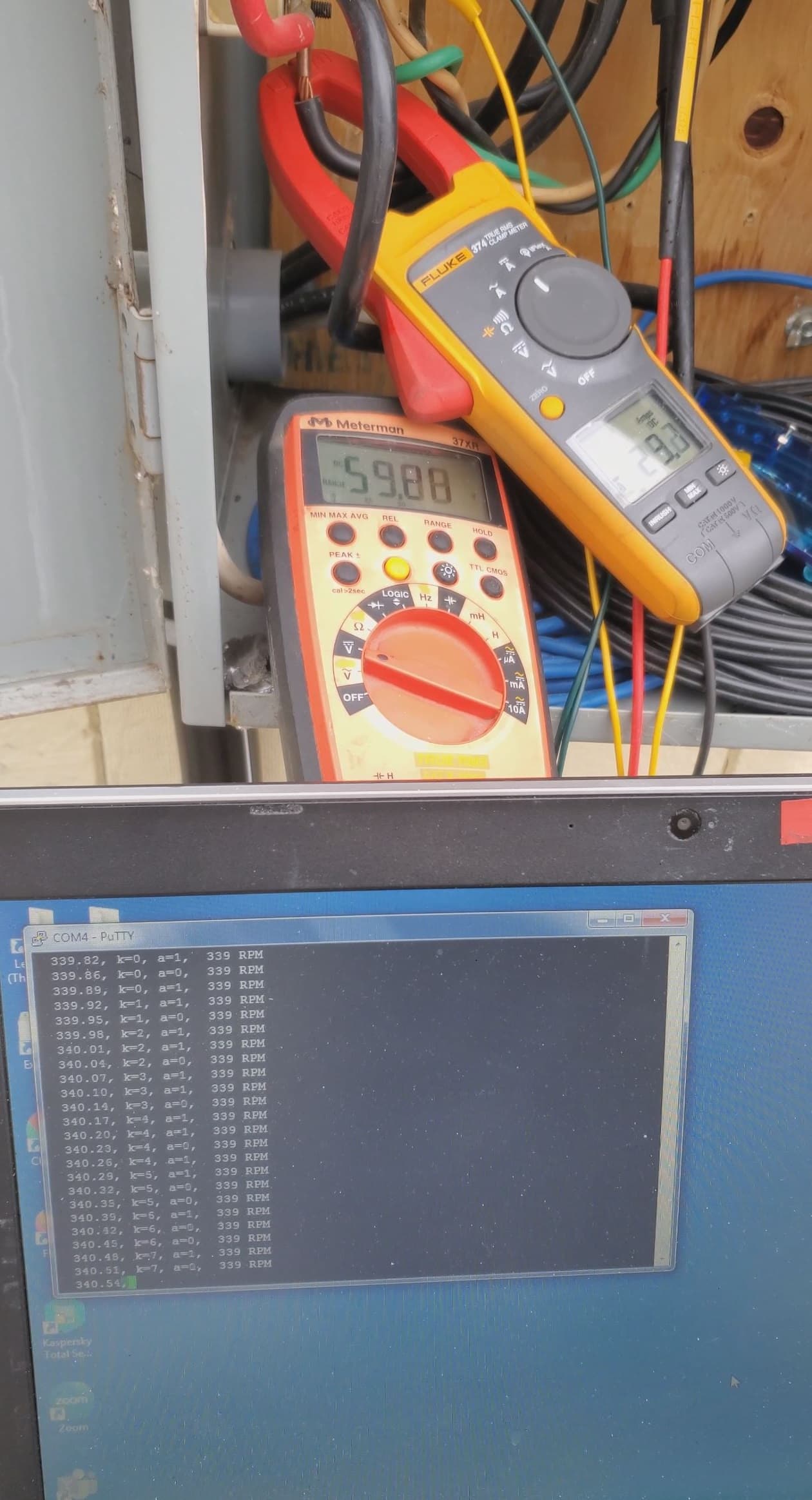
Instead, I plopped 4 resistors (voltage dividers) on a new Arduino Uno, and hooked it up with alligator clips to the turbine’s AC, and presto, the RPM is scrolling across the screen of my laptop. In all about 2 hours of figuring out what to do, doing it, and getting results. Most of it was spent writing the Arduino code.
I didn’t actually think of taking a picture of it - it’s just an Arduino. You can almost see it in this picture but the Fluke is sitting on top of it.
You’re looking at 59.28VDC x 29.2A or 1731W @ 339RPM in the photo below. The Arduino spits out data 30 times per second.
Correct. I sucked the lines of code I wanted to re-use (about 50 lines) from the old datalogger’s program (about 800 lines) and then reassigned hardware ports and pins according to the layout of the Arduino board (using a Uno instead of a Mega makes all the pin assignments change).
I also looked into some features of the Uno that the Mega didn’t seem to have, namely that I can assign interrupt pins to almost any digital pin, not just the 2 or 3 pins with pre-assigned interrupts.
…and as usual missed something in the logical variables making the Boolean logic get “stuck” for a while. Spent a long time trying this and that before finding a relatively obvious answer. I’ll spare you the details, they might not matter, point is as usual when altering existing code it’s still important to review what all of the code does to make sure the changes don’t affect something unexpected.
Next comes the process of building a new datalogger. I picked up a prototyping board that mates up with the Arduino, where I can custom-build several input channels for the tachometer, plus a voltmeter, thermometer, and a current meter. I’m thinking about using a different type of current sensor, but haven’t made up my mind about that yet. Just tired of how really fussy the old ones were.
I also got a colour LCD display, so that I can display the as-measured data continuously.