QUESTION
I am currently working on a design that involves a pipe bridge and pipe supports, and there is some disagreement on how the friction loads are determined for the supports. This is not a typical scenario, as the pipe loop that goes over the bridge serves as a vertical expansion loop. The pipe analysis shows large vertical loads on the two pipe supports adjacent to the bridge (25 kips) which is about 3 times the actual pipe weight. So the thermal loading is pushing down on these supports as the loop expands.
My approach was to use a four column braced frame to resist the friction loads, but I am told it looks ridiculous and is not typical. I used a friction factor of 0.3 which results in a lateral load of 7.5 kips per pipe (total of 2 pipes). The mechanical engineer did not include any friction in their pipe analysis but I took it upon myself to add it into the support design since it will be steel on steel. I mentioned using different materials for the slide supports, and they are concerned that they will not last and do not want to rely on them.
I have not dealt with vertical pipe loads of this magnitude and maybe I am missing something here… Below is a sketch:
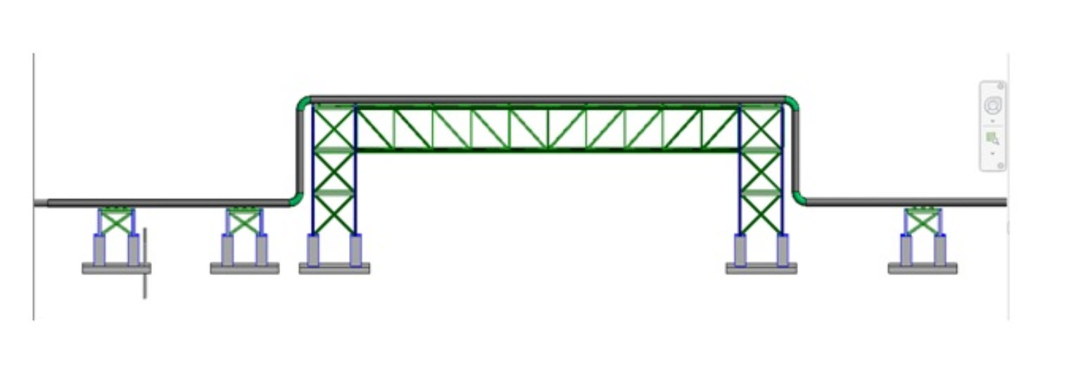
To clarify, the support on the left is an Anchor location. The two supports on the sides of the bridges are slides. After putting some thought into it, the expansion loads are the final loads during operation, and the initial slip and friction force will occur when just the weight of the pipe and water are present. I am sure there will be incremental loading between the initial slip of the pipe and final operational loading, but I think taking 30% of the operation load is too conservative.
REPLIES
JimKSF
Is the 25 kip load due to thermal expansion of the vertical sections of pipe unloading the pipe bridge and transferring the weight of the pipes back to the supports on either side? If so, then whatever the supports end up supporting is the normal force you have to consider for friction.
One thing to consider is that while a 0.3 coefficient of friction is standard for (clean) steel to steel and is often used for pipe supports, most pipes are painted. And most steel supports are galvanized and/or gets dirty/rusty. That can affect the COF. We recently did some tests for COF with a variety of UHMW samples against a 12x12 steel plate painted to the same piping painting specs used at a refinery. There was a wide variety in the results (+/- about 80%) but most of the samples came back with a static COF less than .17. It might be worth looking into for your case.
We modified the ASTM for testing tile materials for friction, using the painted steel plate as the tile and replacing the neoprene “heel” material from Goodyear with the UHMW samples. ASTM C1028 Standard Test Method for Determining the Static Coefficient of Friction of Ceramic Tile and Other Like Surfaces by the Horizontal Dynamometer Pull-Meter Method.
Out loads were lateral and seismically induced. There were anchor stations that took the bulk of longitudinal expansion loads out.
SOURCE
https://www.eng-tips.com/viewthread.cfm?qid=353425
Above is a snippet.