QUESTION
We are working on adding a redundant (M-T-M)substation to existing redundant 72 kV power line circuits, each uses 795 kcmil, “Drake” ACSR. Our load, when added, would result to a line estimated maximum electrical loading of 105 MVA at 72 kV during a CONTIGENCY CASE (WHEN THE BUE TIE IS CLOSED AND ONE POWER LINE IS SUPPLYING POWER TO THE ENTIRE LOADS).
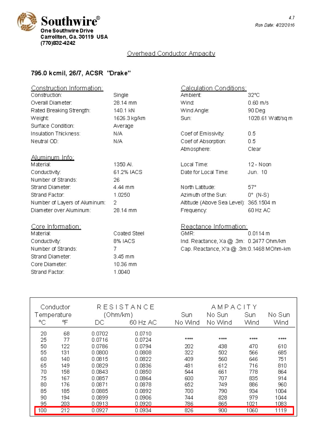
The installed 72 kV circuits are Southwire 795 kcmil, “Drake” ACSR with the ACSR design specification as attached. The design basis for this ACSR was 100 Deg C Conductor temperature at maximum sag with ambient of 32 Deg C with wind and at 1,020 A load current.
However, I would think that when these power lines are already built, the capacity assessment would not use “design values” but worst case minimum. The ACSR data obtained from Southwire lists different ampacities at 100 Deg C conductor temperature and we are at a confusion and debate as which would be used.
Can we use 826 A for normal conditions and use 1060 A for CONTINGENCY CONDITIONS when one power line is down and all bus tie circuit breakers will be closed and one incomer open in all substations fed from these redundant lines?
Our installation is in Canada and the 72 kV power lines are not owned and operated by utility but by industrial plant customer (feeding mining area). Considering that our maximum loading happens in a contingency case, can we consider ampacity on a worst case 100 Deg C conductor temperature as our power line mechanical design and sag is based on 100 Deg C?
REPLIES
bacon4life
You will need to ask the utility what their criteria is. Although the line may have clearances for operation at up to 100C, aluminum starts to loose strength when operated over 90C and many connectors are not rated for continuous operation at 100C. There may either be a lower temperature for normal operations or some other way to limit the loss of life of the conductor to a few 10s of hours per year. I have not heard of utilities in the USA using less than 0.6m/s of wind as the minimum wind speed in the ampacity calculations.
If the line has significant voltage drop or your operating voltage is less than 72 kV, you should also inquire whether the utility uses thermal limits in expressed in amperes or express as MVA calculated using nominal system voltage.
As you are in Canada, 57N latitude drops your solar input a fair amount. Some utilities also use a time slightly later in the afternoon to coincide the typical maximum load/temperature of the day.
I am not familiar with the Canadian codes covering industrial owned equipment. As a general concept, your approach to thermal limits may be reasonable, but it really depends on the owner and/or AHJ agreeing with your design philosophy. If the mine load was 24/7 with planned maintenance on the alternate 72 kV lines done at full load, I would be hesitant to go with 100C ratings. For variable residential/commercial loads where maintenance activities rarely coincide with system peaks, using 100C is more reasonable.
SOURCE
https://www.eng-tips.com/viewthread.cfm?qid=407428
Above is a snippet.