Pressure regulator performance question

Hello everyone,

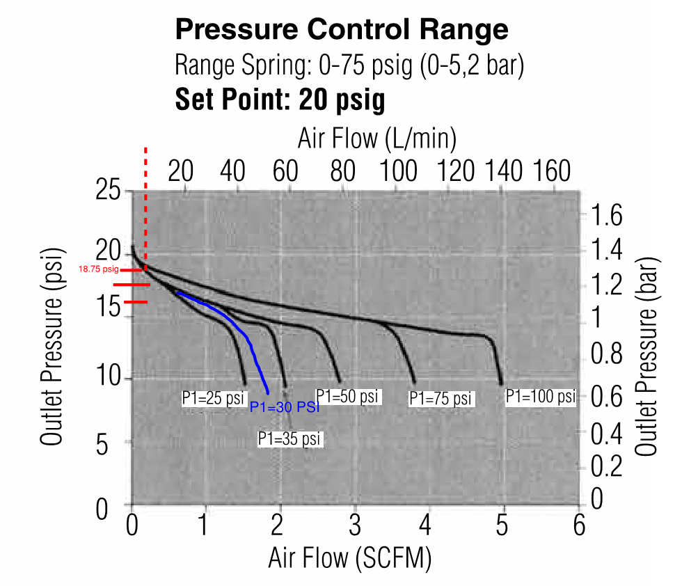
I’ve attached the regulator curve I’m looking at, and edited to include the points of interest. I asked the vendor to send me a regulator recommendation where the inlet pressure (P1) is 30 psig, the setpoint desired is 19 psig, and the outlet flow desired is 17.5 slpm or 21 slpm; I want that particular flow and pressure during flowing conditions. To me, the curve shows that an outlet pressure of 19 psig means a flow of ~10 slpm through the regulator.

I asked the vendor about the curve not supporting the operating point I need, and the vendor response is the following:

In regard to the JSRLFLP chart questions discussed in the email chain below, your approach for creating an approximate, interpolated curve for the P1 of 30 PSI proves on point.
However, it sounds as if you are treating the coordinate point you located on your interpolated curve as a reflection of the capacity limit of the JSRLFP when set at 19 PSIG, which would not be the case.

Rather one should examine the entirety of the curve as that line indicates the Pressure/Flow capabilities and offset (droop) of the trim (Flow Coefficient, Cv) under flowing conditions. Droop remains an inherent characteristic of all self-operated regulators, and thus deviation from set point is to be expected as flow changes.
Based on your interpolated curve, it would appear that the capacity of the JSRLFP with a Cv=0.08 when set at 19 PSIG with an inlet pressure of 30 PSI would hover around roughly 50 SLPM.

The JSRLFP with a Cv=0.08 can certainly handle the 17.5 to 21 SLPM capacities you mentioned in the email chain below. If your goal is to achieve the regulated pressure of 19 PSIG at the point where the flow is 21 SLPM, then, once installed, you would simply have to make certain to calibrate/set the pressure regulator to the 19 PSIG set point under that flowing condition.

The first bolded statement seems wrong because at 50 slpm, the outlet pressure would be around 9 psig, not the 19 psig I need.

I don’t understand how the second bolded statement sentence can be true - isn’t the curve telling me if the regulator is limiting the downstream pressure to 19 psig, then only 10 slpm of gas can flow through it? Also, if we stipulate the behavior the vendor is stating, then the pressure will rebound to some higher value during static conditions, which would defeat the point of having a regulator.

The blue line is my swag at interpolation between the 25 and 35 psi curves. I broke the space between 15 and 20 psi into 4 equal segments to make the minor gradations.

How much excess pressure (over your 19 psi) are you prepared to tolerate downstream of the valve when there’s no flow? Is that a requirement you’ve discussed with the vendor?

I’d say more like 5 slpm. And, the rep is FOS!

I don’t have much allowance for higher than 19 psig- maybe 1 psi higher, which I don’t think is a realistic margin to work in for this.

Do you think my assessment of the regulator performance is correct or am I missing something?

Your assessment is correct. Is the supplier Steriflow? Do you require sterile construction? I would look for a different supplier. Does Fisher have something that will work?

Yes, it is Steriflow and the client already has this style regulator which is why I started there. I have other vendors I can go to, but my company has used Steriflow products before so the other engineers didn’t have any pause.

Sanitary construction is necessary for this service (supply to bioreactors), and I plan on checking with Emerson if I can’t get alignment with my Steriflow rep.

I am confused as to what the confusion is. As the vendor said droop is a characteristic of all pressure regulators. The regulator, by itself cannot control both flow rate and pressure simultaneously. There has to be some other flow control valve or restriction. When the flow rate is what you want you adjust the regulator to 19 psi. The curves you post simply show how the actual outlet pressure of the regulator droops as flow is increased (with the regulator set for 19 psi when the flow is almost zero. If you want 19 psi at a higher flow rate you simply adjust the pressure upward. Then you will get more than 20 psi at almost zero flow

Instrument grade regulators can be designed to have less than one percent of the droop of your selected regulator.

Unless you have a self-relieving regulator, the outlet pressure can rise to full inlet pressure if there is no flow demand from your process, and the regulator valve leaks. Note the sharp increase in pressure at zero flow in your chart. This is because the regulator valve does not seal tightly until the pressure rises several psi above set point. If dirt gets in the valve it will never seal completely.

Most pressure regulators are rather crude devices that work fine within a certain range of flow rates, but do not expect them to function at all when you get to almost zero flow, like when you close a valve on the outlet.

I think

says it all.

It seems you want flatter curves. This implies a bigger diaphragm and bigger regulator to me.

I’m not saying that the droop shouldn’t exist, I just normally don’t see the chosen operating point so far into the droop region. It seemed to me the vendor was saying I would achieve pressure and flow combinations that the curve didn’t support - that was my main issue.

The gas delivery layout has changed, so I’m going to be starting from scratch and picking a new regulator. It will be larger to accommodate a new higher flow rate, and hopefully the line of regulators for my new pressure and flow combination will have flatter curves.

I agree that the regulator can’t control both pressure and flow, but I think there should be a regulator that has a closer fit for my operating point. I will have to look into the amount of positive pressure deviation I can have - the 1 psig margin is too tight.

jari001, your logic still appears to be confused. Your “operating point” is within the capacity of this regulator. It is simply that the droop is greater than you want. You have two operating points that you want to be on the same curve. These two operating points are the same pressure at different flow rates. That defines the curve as a flat horizontal line

Here is a link to a precision regulator:

You can also use a “volume booster” to get any flow you want from any regulator:

I only had one desired operating point - either 17.5 slpm @ 19 psig or 21 slpm @ 19 psig. The first represents a diversity factor of 70% to the bioreactors while the second point is 100% of possible flow demand. Maybe I was unclear in my post or am I missing something?

Thanks for the recommendations on the regulator and volume booster (never seen that before), but I don’t think they will be appropriate for sanitary/sterile service.

My instrument training was a long long time ago, but we always used a flow loop to control flow and a pressure regulator to control pressure.
Trying to do both jobs with a pressure regulator may be sacrificing some precision.
In support of Latexman, try a larger regulator.
Where is the gas going?
How much restriction at the receiving end?
If you control the pressure, the end restriction will determine the flow.
If you control the flow, the end restriction will control the pressure.
You can’t control both pressure and flow in one line.
Your vendor was trying to explain droop.
Basically the flow through the regulator creates a pressure drop across the regulator.
You compensate for this pressure drop by progressively higher set points for higher flow rates.
To control the flow, you need a flow control loop.
Once you have established a proper flow control, you may install a pressure regulator upstream to limit the maximum pressure to 19 psig.

@WaRoss
These regulators that the client already has have exposed me to very droopy curves. Previously I have worked with regulator selections that had much flatter pressure vs flow curves such that I could find a regulator that had my desired flow and target line pressure point on it’s curve. Granted these were different manufacturers and non-sterile services.

The path I’m on now with the vendor is to see if there are pilot operated regulators. I understand having different equipment for pressure and flow control (e.g. regulator followed by a rotameter), but if I can’t find a regulator with the right curve, I will have to pursue a setup like that.

Your requirements on pressure/flow are very challenging for this. Good luck, and let us know the outcome. My applications usually have much more “slop” than yours. Sometimes our predecessors and tightening requirements box us in.

I am crossing my fingers to hear back from the lead engineer that knows more about the bioreactors that the range of supply pressures isn’t as tight as I’ve been working with (previous design) - I’m thinking ultimately what matters is mass of gas in must be sufficient and not the combination of mass and energy at the bioreactor inlet.

The point that I am trying to make is that the process will have a resistance to flow.
At a given pressure, the process will determine the flow.
If you control the pressure, the process will set the flow.
If you control the flow, the process will determine the pressure.
To control the flow, use a mass flow meter such as is used in automotive engines in conjunction with fuel injection.
That will control the mass of gas admitted to the process.
The pressure will be what it will be.
A low droop pressure regulator may be used to avoid over-pressures.
If such systems were working in the past, I suspect that the pressure and flow rate were never measured accurately and compared when in use.
I don’t deny that such a system appeared to work in the past.
I suspect that;

  1. A fortunate choice of components delivered enough gas, but the system was not optimum.
  2. The actual pressures and flows were not measured accurately in operation and were not what the operator thought they were.
    While Ohm’s Law is specifically for electrical systems, the basic principle may be applied to many systems.
    “The current or flow in a system is directly proportional to the voltage or pressure and inversely proportional to the resistance to the flow.”
    Neglecting line losses, the pressure may be taken as the primary supply pressure and the resistance as the combined resistance of the .regulator and the process resistance to accepting the gas.
    or
    The pressure may be taken as the pressure after the pressure regulator and the resistance as the process resistance to the gas.
    These variables may be non linear, however at any given combination of pressure and resistance to flow, the pressure and resistance will determine the flow.
    When a system is working by coincidence, any changes, scaling, or replicating with different hardware is subject to unintended consequences.

Yes, that is what I have been suggesting.
I think that you are on the right path.
Control the flow to optimize the process.
Then provide over-pressure protection.
Your response indicates that my words may not have been in vain.