QUESTION
We recently installed internal floating roofs (IFR) of the full-contact type in two new 150,000 bbl. regular gasoline tanks (145’ diam. by 56’high). The IFRs were hydro tested per the request of the client. They were floated to the tanks critical height with successful results. After a couple of months of the tanks being in operation, we are seeing wet spots of gasoline at two locations in both tanks. The wet spots are on the sketch panels near the ATG ladder well and the other in the panel were a gauging cone is located. These are the panels with the largest perforations, and of course they do have a seal. Here are some observations:
- Both IFRs have primary mechanical shoe and secondary loop seals.
- Designed for 8,000 bbl/hr.
- Climate right now is very hot, and we are seeing temperatures in the fixed roof (steel dome) in the 130 deg. F.
- Temperature probe in the liquid is reading 87 deg. F. Probe is located in the in a well pipe in the center of the tank (from the tank roof all the way down to the tank floor).
- IFR panels have drain holes.
- Panels are 4" thick.
- Observations have been made and no sign of loop seal failure are visible.
We are consulting this issue with the IFC manufacturer, they claim they have never seen this type of situation. We think two things may be causing this issue: (1) either operation is injecting somehow air in the inlet line, from transfers or from the vessel, or (2) the product temperature near the tank shell is higher than in the tank center and thus is near or at the boiling temperature causing vapors to sip through the ATG seal or through the panel drain hole. We continue to monitor the situation to fix the problem.
Has anyone here have had this situation before with this type of full-contact covers? This is the first experience with full-contact covers, all our experience is with pontoon-type covers.
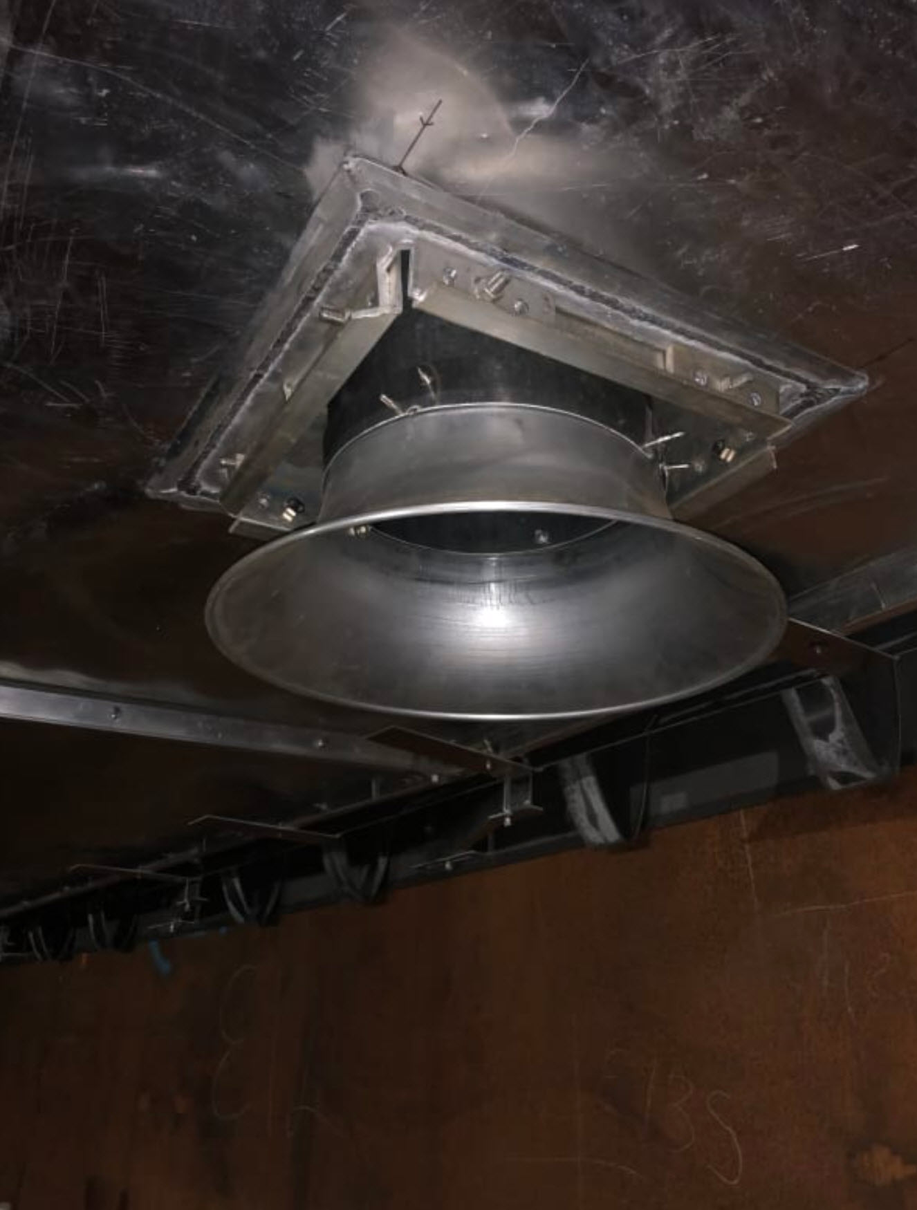
The ATG and gauging cone penetrations are at 36" from the tank wall. Both are at 180 deg. apart. Here’s the IFC section drawing. The panels are actually less than 4" thick. Jamming by an obstruction is hardly possible, but by thermal expansion could be a possibility:
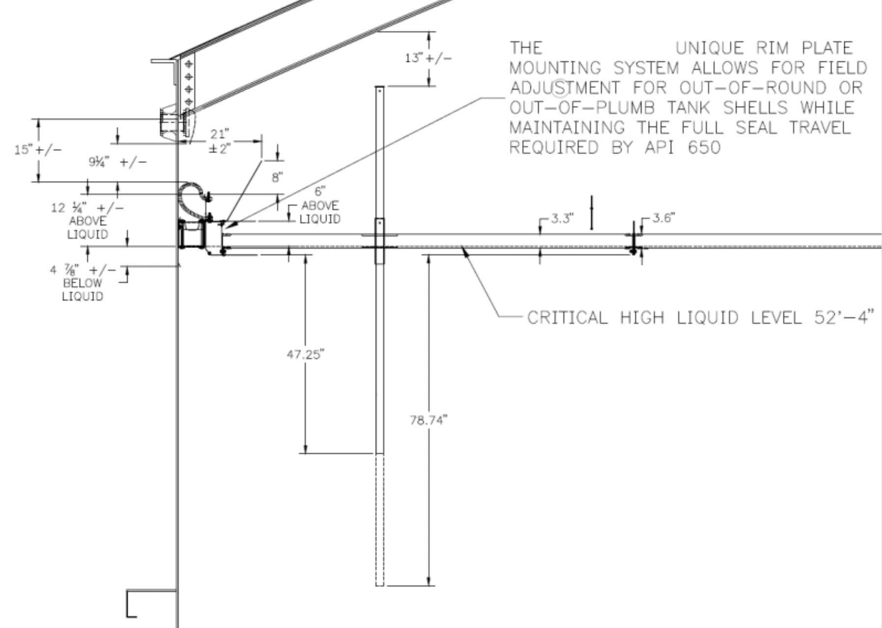
The IFC is made of aluminum 3003. Panels are hollow with a 0.023" thick skin, no honeycomb style. Prior to fill the tanks with gasoline, client insisted on hydrotesting the tanks once the IFC were installed. They were in contact with water for more than 60 days, from filling up to emptying, although we cautioned them about corrosion even after 4 days of contact with water. A temporary cathodic protection was installed to mitigate corrosion on the IFCs during the hydrotest. Here are pictures of the ATG and the sampling cone. It is basically a “giant pontoon”. The IFC manufacturer claims that that it is designed for a buoyancy 5 times of that required by API 650. There is nothing inside the panels, other than aluminum extrusions to provide support. These are NOT honeycomb sandwich panels:

Thoughts on what could be happening? Thanks in advance for your input.
REPLIES
IFRs
This type of roof is not very common. Did you buy their first ones? If the manufacturer has not seen this type of issue, they are also new to floating roofs. You spent a lot of money and have a right to be at least a little disappointed in the performance of the product and the failure of the vendor to help.
Not a root cause, but your buoyant depth is somewhere between 3.3" and 3.6", not 4" as some have suggested.
There are really only two reasons for liquid to be up on the deck - the deck is floating low in that area and/or there was turbulence (during the initial fill, pigging or blending activities)
You’ve got plenty of buoyancy overall. The seal is a truly unique one that I have not seen in my 42 years so I can’t comment on its friction but that does not make it a bad one.
From your description, I’d suspect one or more of the following:
- Panels in general leaked during the hydrotest which you would not know because of the top skin, that could have reduced buoyancy.
- The panels with the penetrations leaked during hydro or product and you won’t know because of the top skin, that could have reduced buoyancy.
- The rim seal friction no doubt contributed but should not really have held the roof down unless a tank shell irregularity substantially reduced the rim space and increased seal friction. However, seals should be designed to accommodate +/- 100mm [4inches] without greatly increasing their friction.
- The friction of the seals on the poles and ladder no doubt contributed but should not really have held the roof down. The ladder rungs do present obstructions but the ladder seal should have been designed with this in mind and have sufficient compliance to not increase the down force greatly.
- Aa product burp, blending, mixing, etc could have splashed liquid up through the wells but should not be a recurring event
Questions:
- Are these two penetrations close to each other?
- Are these two penetrations close to the rim?
- Does the rim space vary as the IFR goes up?
- Was a tank shell survey done prior to the IFR installation as required by API 650 H.6.1 - this would have identified pinch points
- Do the wet spots change in size or location as the liquid level changes?
- Are you sure it is product and not water dripping from the fixed roof?
- After hydrotest how were the panels examined to be sure they were empty?
- Are there drains in these panels, was the liquid around the drains?
- Were 10% of the flotation compartments field tested per API 650 H.6.4, if any leaked were 100% testd?
- How were the seams between panels tested, see API 650 H.6.2?
- Did anyone walk on the IFR during hydrotest and confirm the flotation freeboard, can that be done on product?
- Are any other penetrations leaking?
- Does the terminal operation include pigging or blowing the lines clear?
- Is there a mixer (jet, propeller, eductor) anywhere near these penetrations?
Other comments:
- 0.023" sheet is not easy to weld and test
- Thin material is subject to shipping and field damage
- Thin welded material is not very strong
- There are miles of weld exposed to the liquid
- There may be difficult corners to weld and test
- It is not clear where the structure is, how strong it is in both directions
- It is not if the IFR was installed level, this affects how deep in the liquid it floats locally
SOURCE
https://www.eng-tips.com/viewthread.cfm?qid=458330
Above is a snippet.