How the control scheme in the steam generator is working with three control elements?

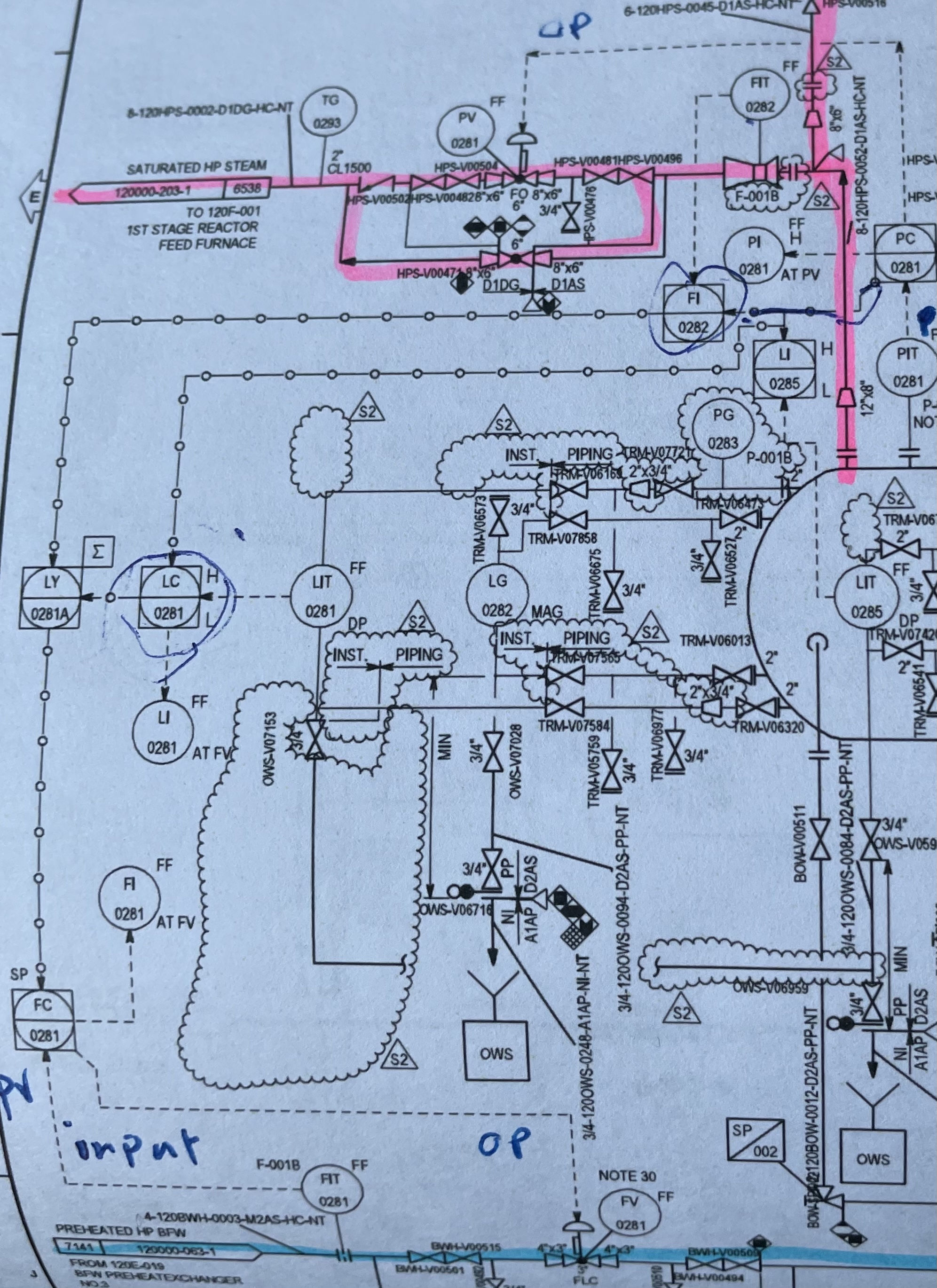
This is the “Loop Sheet” diagram. Can you post the physical P&ID too?
This may help:
Steam Generator Level Control.pdf (1.4 MB)
PC-0821 is a standard feedback control loop. It does pass it’s PV on to FY-0282 and LY-0281B for their use.
LY-0281B, LC-0281, LY-0281A and FC-0281 are basically doing a material balance on the steam drum to anticipate changes and control the BFW flowrate.
If there is some code you can look at, it may become clearer for you.
The pdf is from Process Control Systems by F. G. Shinskey.
Your level control is exactly as Fig. 7.2. As mentioned, the pressure control is a standard feedback control loop. The steam flow math needed the pressure to do it’s calculations to get the flow rate. The level control math is using the pressure along with BFW flow in and steam flow out to do the material balance.
Why the water level inside steam generator measured by differential pressure there is any relation between water density and actual steam?
There are relationships. If one knows the sat’d steam pressure, one can know the sat’d steam temperature (vapor pressure equation or steam tables). Inside the drum we assume T steam = T water. If one knows the water temperature, one can know the water density (equation of state or steam table).
Your code (DCS program language) will show you how detailed the designers got, but I suspect they kept that part simple. Compared to water density, steam density is very, very low, so we usually neglect the steam density in a steam drum level instrument calibration. The level instrument is probably calibrated to the water density that corresponds to the T and P the steam drum normally runs at.
For example, say this is s.g. = 0.9. When dP = 0 = 4 mA, no 0.9 s.g. water. When dP = 100% = 20 mA the space between the upper and lower nozzles is full of 0.9 s.g. water.
What is your steam pressure set point?
Steam pressure 42 bar
So from steam tables, the sat’d water density is 49.43 lb/ft^3 (s.g. = 0.7926) and the sat’d steam density is 1.35 lb/ft^3 (s.g. = 0.0217). Ignoring the steam density only adds a maximum of 2.7% error at 0% full in the calibration. At 100% full, there is 0% error (no steam between the taps). Not worth the complexity of including the steam density, in my opinion.
So the actual steam and water density shall be calculated by the DCS system using the standard characterizer blocks converting the actual steam generator pressure measured by PIT-0281 to the steam and water densities at actual pressure.
So why density of water is important some steam generator or steam drum, water density not used?
What % level is normal set point?
50%
In the control scheme the mass balance around the steam drum can be done with a signal that is proportional to the mass flow rates of BFW in and steam out. That’s why you see the square root (DP) operator in the .pdf. One does not have to have the density of the BFW and steam.
However, in the calibration of the level the density of the sat’d water can be used for a reading with 1.35% error at 50% full. And alternatively, in the calibration of the level the density of the sat’d water and sat’d steam can be used for a reading with 0% error at 50% full. What I was trying to explain is most people would be satisfied using just the sat’d water density and the actual level would be 50.7% when the level instrument read 50%. Not much difference, and it will work just fine. It is more important for instruments to be repeatable than accurate.
Thanks a lot latexman
Three-element control is utilized to maintain steam drum level at usually >20% MCR (Maximum Continuous Rating) to combat “shrink” and “swell” in the drum due to load swings in the steam system. As demand for steam grows or shrinks quickly (within minutes, for example), the pressure in the drum can quickly increase or decrease. Assuming the firing rate of the boiler is the same throughout the swing (typically it is), then the drum level will either “shrink” due to increased header pressure (reduced demand) or “swell” due to decreased header pressure (increased demand).
This shrink/swell phenomenon, with a large enough swing, can (and has in many cases, especially on boilers with smaller drum volumes) caused the steam drum level to exceed safety trip points (either low-low level or high-high level) and trip the boiler.
By density compensating (with pressure @ saturation conditions) the feed-forward-plus-feed-back control loop, the controller can be tuned to respond automatically to these shrink or swell conditions (the feed-forward signal typically being the steam flow).
What do you mean density compensating?
Because as per P&ID signal from PT and another signal from FT it will goes to another block.can you give me more details about density compensating .
Thanks
As we all know, the density of water varies with temperature and pressure.
In your particular example here, the pressure reading from PIT0281 is being used to compensate the value of FIT0282 for the steam flow to account for the actual flow of steam leaving the drum (as well as the density of water observed by the level transmitter LIT0281 for the drum) - in doing so, you’ll have a much more accurate look at what’s happening at a given moment; recall that the change in steam demand also affects a change in pressure in the drum and this change in pressure will affect the density of water/steam as well. By compensating your measured values against the actual density at that moment, you’re able to more accurately control drum level and prevent inadvertent shutdowns due to low-low or high-high level trips. Keep in mind, the density of feedwater being introduced is known and relatively constant.
In other control designs, it’s also common to compensate with temperature readings, on top of the pressure readings, when superheated steam is involved - I assume that isn’t the case here.
Thanks dear for your sharing.Here it’s not compensated with temperature.what do you think incase of steam flow production FIT reading zero may can be happen due to FT malfunction boiler feed water will close or not?
Because steam flow and boiler feed water should be equal.
And how we can bypass three control elements here incase of FT malfunction?
Whats the purpose of Feed fordward controller?
Do you have a control narrative for that control loop that you could share? or a SAMA logic diagram perhaps?
I would need to understand the current logic of your control loop to answer most of your questions (in short, it’s dependent upon how that control loop was programmed into your DCS).
The purpose of the feed-forward controller is to factor in the density-compensated steam flow into the control of the boiler feedwater level control valve’s position. Note that, in general, the boiler feedwater flow required is equal to the steam flow out of the drum + the continuous blowdown flow leaving the drum.