If iam doing it right the digital meter shows 1.
Please let me know if that is the correct way or not. I searched the web but every one that does those videos talk as if i understand what they are talking about and i don’t. 
If iam doing it right the digital meter shows 1.
Please let me know if that is the correct way or not. I searched the web but every one that does those videos talk as if i understand what they are talking about and i don’t.
We’re getting closer.
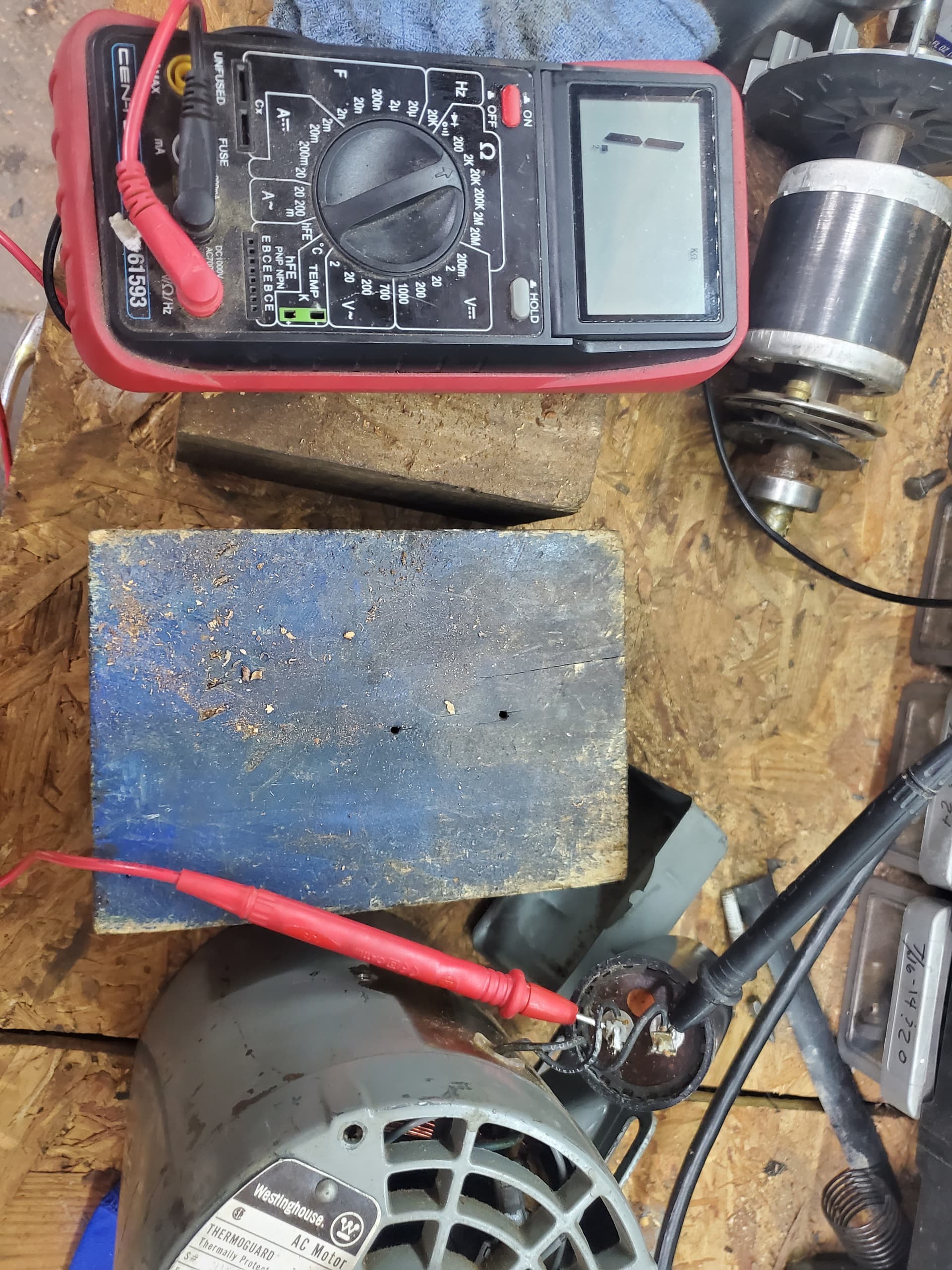
You have the Ohmmeter on the 2 k Ohm and are reading i, or i k-Ohm.
That will be the internal discharge resistor at 1000 Ohms.
Unfortunately that tells us nothing about the condition of the capacitor, except that it is not shorted.
Re-read my last post and look for the cgarging pattern on the meter.
For a good capacitor, the reading will start at or close to zero Ohms and rise to the value of the discharge resistor (1000 Ohms or 1 k-Ohms).
Reverse the leads and see the same rise again.
To check the start switch:
There should be no continuity between the red and the black wire.
On the circuit board, there is a brass spring strip with a lighter coloured strip riveted to the brass strip.
When you depress the end of the strip that is opposite to the end with the black wire, you should get continuity (zero Ohms or close to zero Ohms) between the red and black wires.
if there is no continuity, clean the contacts on the other side of the circuit board.
Next, examine the centrifugal mechanism.
Move the weights outward and confirm that the disk on the right, towards the bearing, moves easily.
The weights are the round, brass coloured devices with the raised ridge around the center.
When assembled, the disk towards the bearing should bear against the strip on the circuit board and there should be continuity between the red and black wires.
When the motor is at rest, the disk should bear on the switch and there should be continuity between red and black, putting the start winding and capacitor in the circuit.
When the motor comes up to speed, the disk should be clear of physical contact with the switch strip on the circuit board so that the start winding and capacitor are out of the circuit and there is no wear of the disk or of the switch strip.
Your bearing may be over-greased.
I have read your reply several times and Iam sry but like i said in the beginning i do not understand electrical. This is the one thing i need someone to stand over me and tell me what to do step by step. I don’t know on the my multimeter under ohms what 200, 2k, 20k, 200k, 2m, or 20m even means or how it supposed to tell me what i need to know to post out here. I have read other sites to try and help me and none of them helped. All sites that try to explain the process, they expect people to have some competence of what they are doing and i don’t.
I think the problem is with the 2 wires that are from the circuit board and the windings that is causing me the problem. Since i don’t have any pictures of how it was wired up prior to me removing it, i don’t know how to wired it back. I have since just put it back together and i am just going to put my disk sander back together with the same crappy motor that came with it.
I do appreciate the help you all provided but i have to many other projects to do to continue to try and understand something my brain just doesn’t get. Plus i need my sander back…
lets start with the Ohmmeter.
The highest number on your Ohms scale is probably 200, meaning 200 Ohms.
This is the scale that you will use to measure continuity.
Continuity will be very low, just a couple of Ohms or less.
You will read Ohms directly; 40 = 40 Ohms, 150 = 150 Ohms etc.
2k means 2,000 Ohms full scale. When on the 2k setting, multiply the readings by 1000. (A reading of 200 becomes 200 X 1000 = 200,000 or 200k)
20k, 200k, 2m and 20m are full scale values.
Multiply the readings by 10,000, 100,000, 1,000,000. and 10,000,000 respectively.
These scales are not much used in motor use.
While insulation values range up into the meg-Ohm range, a multi-meter is unsuitable for measuring insulation resistances.
Tip: Short the probes together. You should fed zero or close too it. If the reading is not exactly zero, that reading will be your new zero.
Tip #2: For this work, relative readings are more important than absolute readings. We often don’t know what the reading of a new component was anyway.
So, short the leads and note the reading.
That is your true zero point. Good continuity will be very close to that point.
Some windings have only a few Ohms resistance. They will read quite close to true zero but not as close as a closed switch.
I had a long day and I’m really tired. Ask me again tomorrow.
Also, get used to what the display looks like when the leads aren’t connected to anything. Different meters have their own ways of saying “That’s more than I can measure with that range selected” . What you showed in your photo may well be that, rather than a reading of “1” - which would normally appear at the right hand end of the display.
That looks like an open circuit reading to me. I wonder, for those range settings at the left, if F could mean Farads. Could be interesting to try on that capacitor.
Thanks for all your help guys, I do appreciate it! Before I gave up Saturday afternoon I was able to get this video. I could not post it until after I made it back to my Laptop in the office. Apologies for being upside down, it was the only way I could get the video.
https://drive.google.com/file/d/1teBKnjLQf1sVdIEZRuTBKBI8mG2gXb50/view?usp=sharing
That was the only thing I got out of the capacitor. I have the meter on 2K and it always reads 1 when I am doing nothing.
The capacitor may have an internal 1k Ohm discharge resistor.
The rolling numbers when you reverse polarity are a good sign.
I looked at the video again. a “1” when the leads are open is probably an indication of over range.
It always reads 1 no matter what setting the meter is on. Which is another confusing aspect of what I have read versus what I see.
Correct me if I am wrong, but it looks as if the 1 is too the left of the scale. That is, the most significant digit, rather than the least significant digit.
If it were a reading of 1, you would expect the 1 to be the least significant, or to be followed by a decimal and following zeros.
From the information that I have, it looks like an over-range indication.
What is the reading when you short the leads together on the various scales?
By the way, a normal reading on a capacitor is infinity or over-range. If there is an internal discharge resistor, the normal reading is the value of the discharge resistor.
When the leads to a capacitor are reversed, the capacitor discharges through the meter. This will give a rolling reading that starts at zero and increases to either the value of the internal resister or to infinity. (Over-range)
If you notice at the beginning of the video I did reverse the leads and nothing happened. That’s when I realized I had them reversed.
I suggest that you watch the video again.
[quote=“WaRoss, post:31, topic:3392”]
By the way, a normal reading on a capacitor is infinity or over-range.
When you connect the leads, your meter shows over-range. This also indicates that there is some residual charge from previous testing.[/quote]
Because of the rolling nature of the reading, the zero may not be displayed.
Then you reversed the leads.
Your reading starts at 0.316 Ohms, the reading increases to 1.998 Ohms. You are on the x1000 scale so the actual values are times one thousand.
The readings and indications are normal for a capacitor.
Oh, I didn’t realize that could happen from simply testing it. I learned that much .