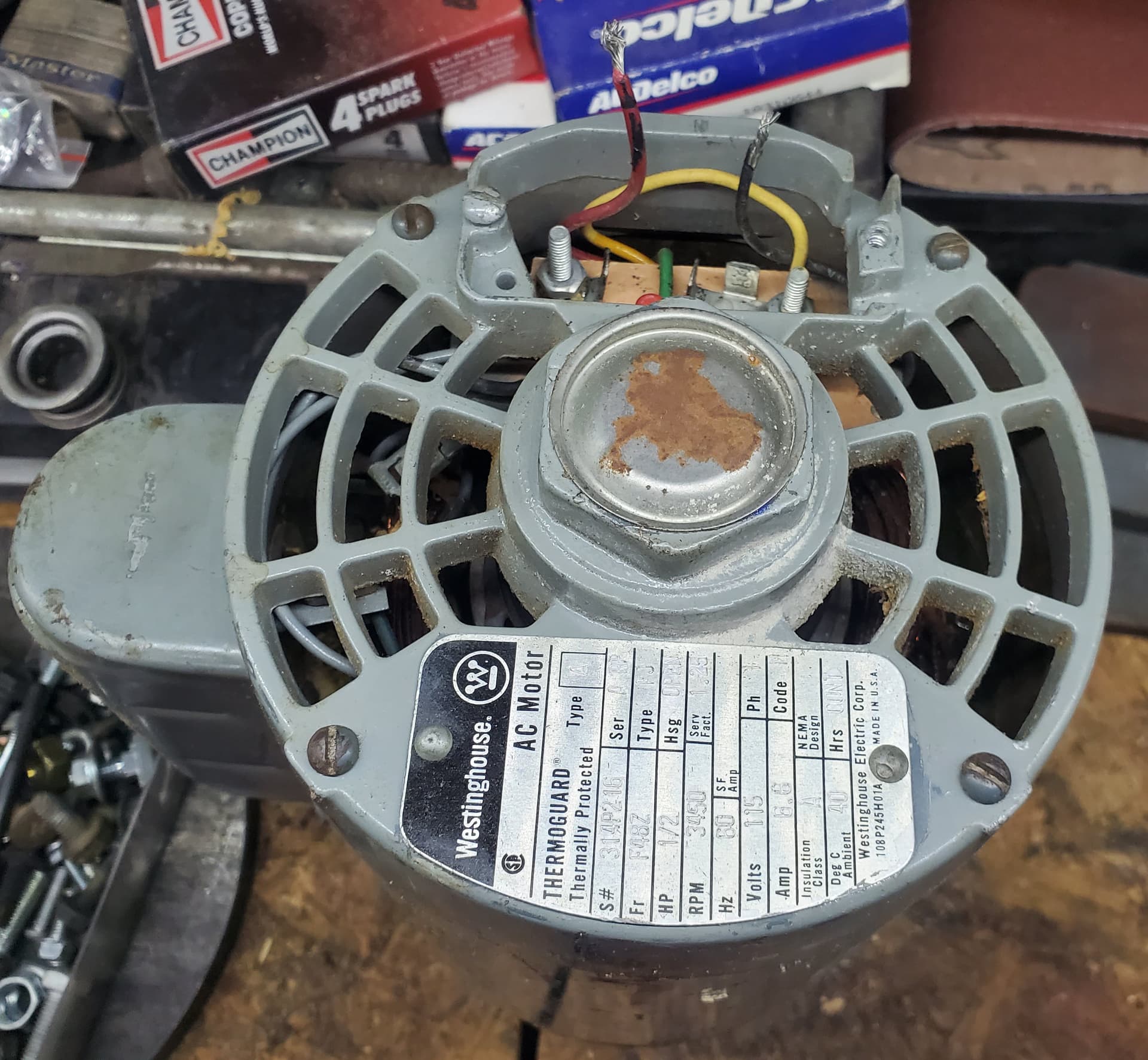
I have an older Westinghouse AC electric motor that came off my Wife’s Grandfather’s old makeshift table router. I removed the motor to replace the one on my Belt\Disk sander, but now I cannot get it to come on. When I put power on the tabs on the board it just hmms.
When it was installed on the router there was an on\off switch and what I think was a 3-way switch. I don’t know if it controlled forward/back or variable speed. I just want the motor to go full speed in one direction.
My knowledge of electrical is very limited hence is why I am out here to see if anyone can help me figure out how to hook this motor up without burning down my house.
Well, it hums, so either the thermal protector has not failed ope or the thermal protector is not wired in the circuit.
The first thing to check is the starting winding and circuit.
Turn the motor on and immediately spin the shaft.
You can often get enough spin by flipping the pulley by hand.
If the motor starts, we will go back and trouble shoot the starting circuit.
If the motor does not start, turn it off immediately.
A stalled motor may burn up in less than a minute.
No test equipment outside of a multi-meter that I only know how to read for DC.
It seems to spin fine when there is no power. It’s not super free, but it does spin.
I put power on it last night and it started to slowly spin with me spinning it manually, but it only lasted a couple of seconds and went back to humming.
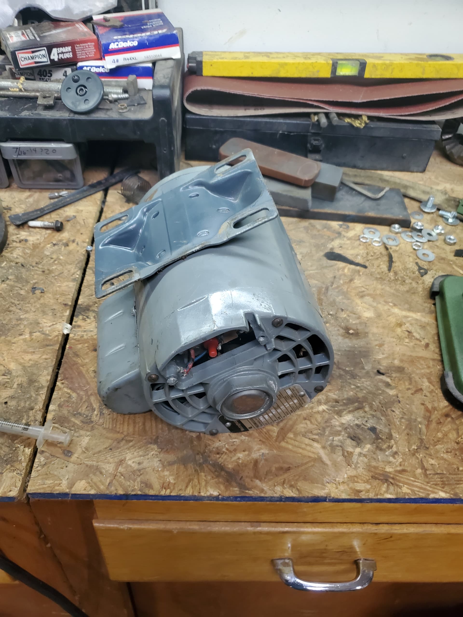
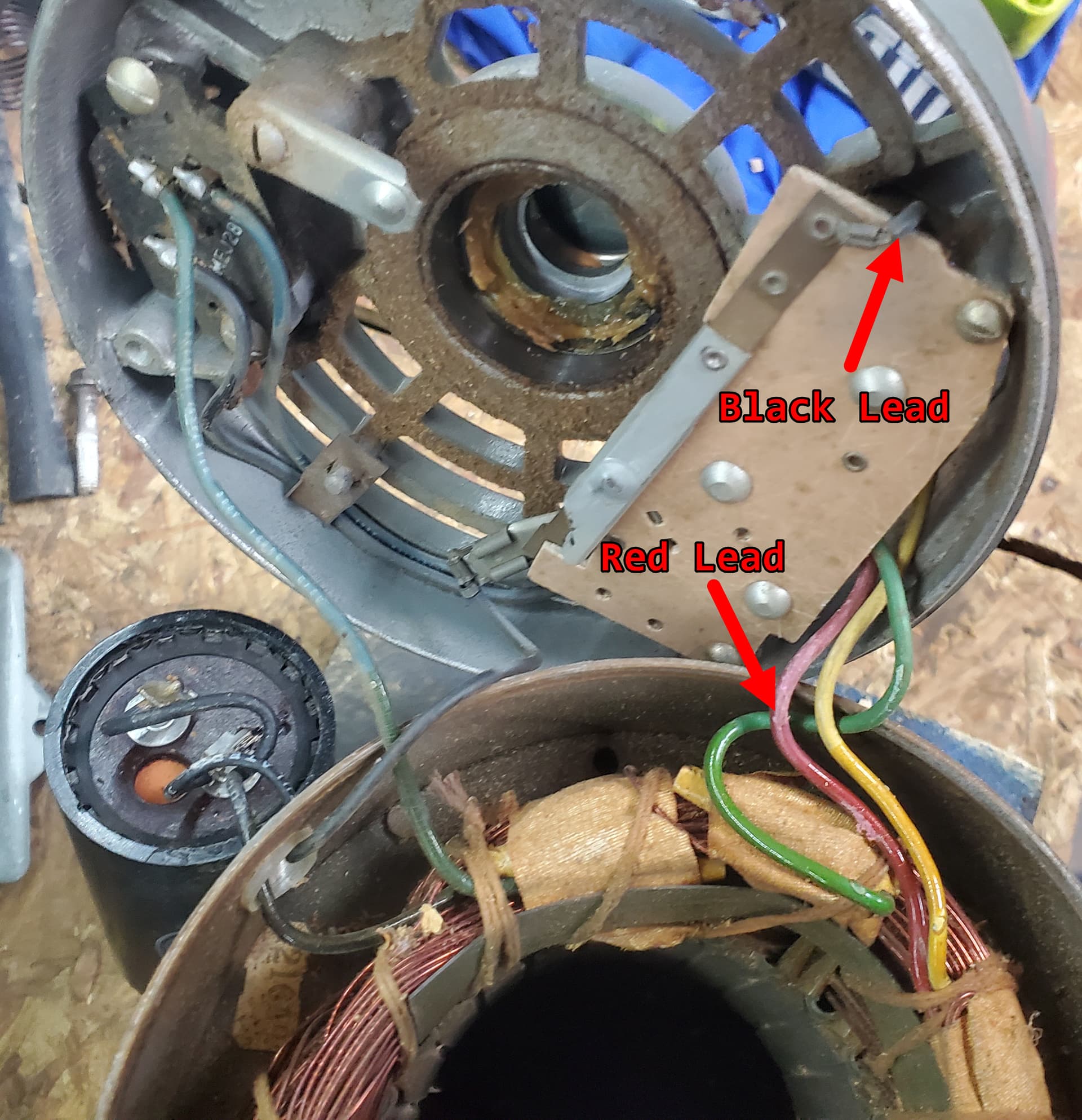
Take the end bell off of the non-drive end.
There are four through bolts to be removed.
The end bell will be connected to the stator windings by the wires.
Be careful not to damage the wires.
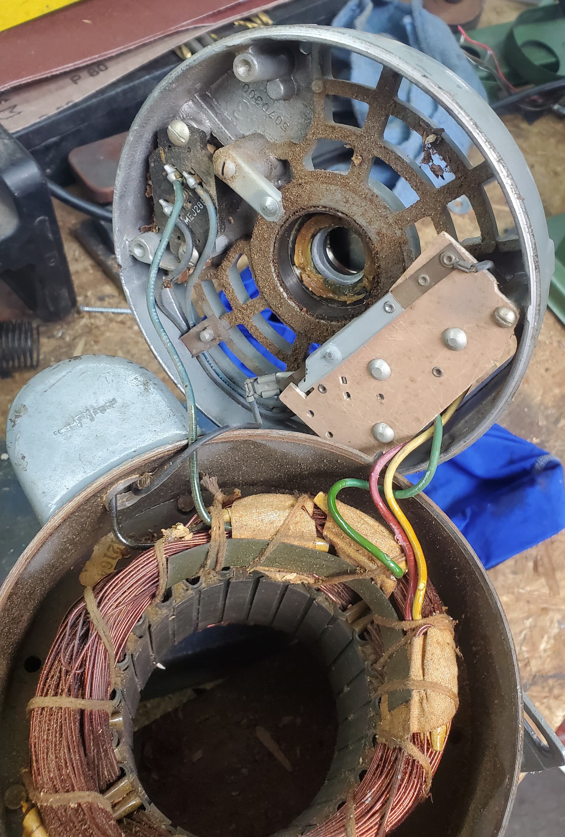
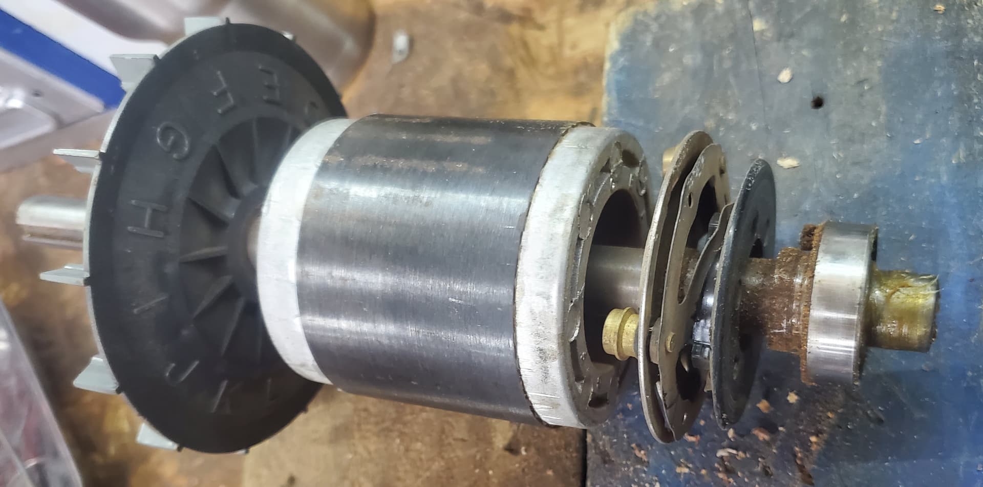
You should find a centrifugal mechanism on the shaft.
Typically this will be two weights of some shape held together by two springs and a movable collar.
When centrifugal force extends the weights the collar should move towards the end of the shaft.
Move the weights manually and verify smooth action with no binding.
Next:
On the end bell there will be a U shaped flat spring.
There are generally anti-friction pads on the ends of the U arms.
The movable collar contacts these pads when at rest and at slow speeds.
At operating speed the collar pulls away from the U and there is no physical contact.
The collar contacts the U when at rest and when starting and stopping and wear is kept to a minimum.
That notwithstanding, I have seen wear on these devices on motors with a very high number of start-stop cycles.
Finally, there is a set of starting contacts under the U device.
The primary cause of the symptoms that you describe is contamination of these contacts.
Inspect and clean these contacts.
Unfortunately, the secondary cause of your symptoms is when the primary cause has gone unrepaired and the starting winding burns up.
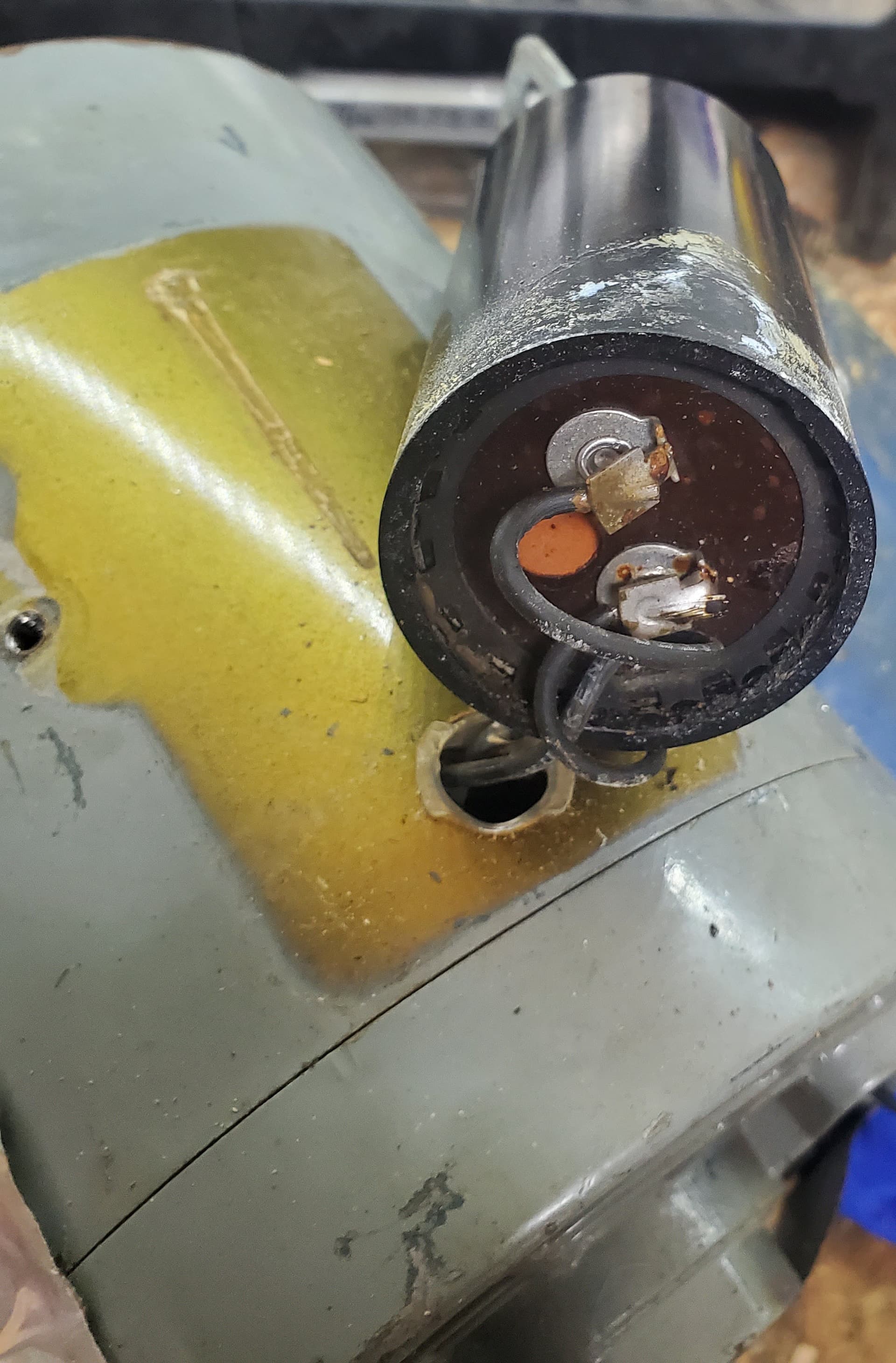
A starting capacitor is about 3 inches long and about 1 1/2 inches in diameter.
It will be mounted on top of the motor in a little can, held on by two #8 screws.
If the motor had a capacitor and the capacitor has been removed, you will see two screw holes in the top of the motor and a hole through which the leads entered the motor housing.
Often the paint will be less faded.
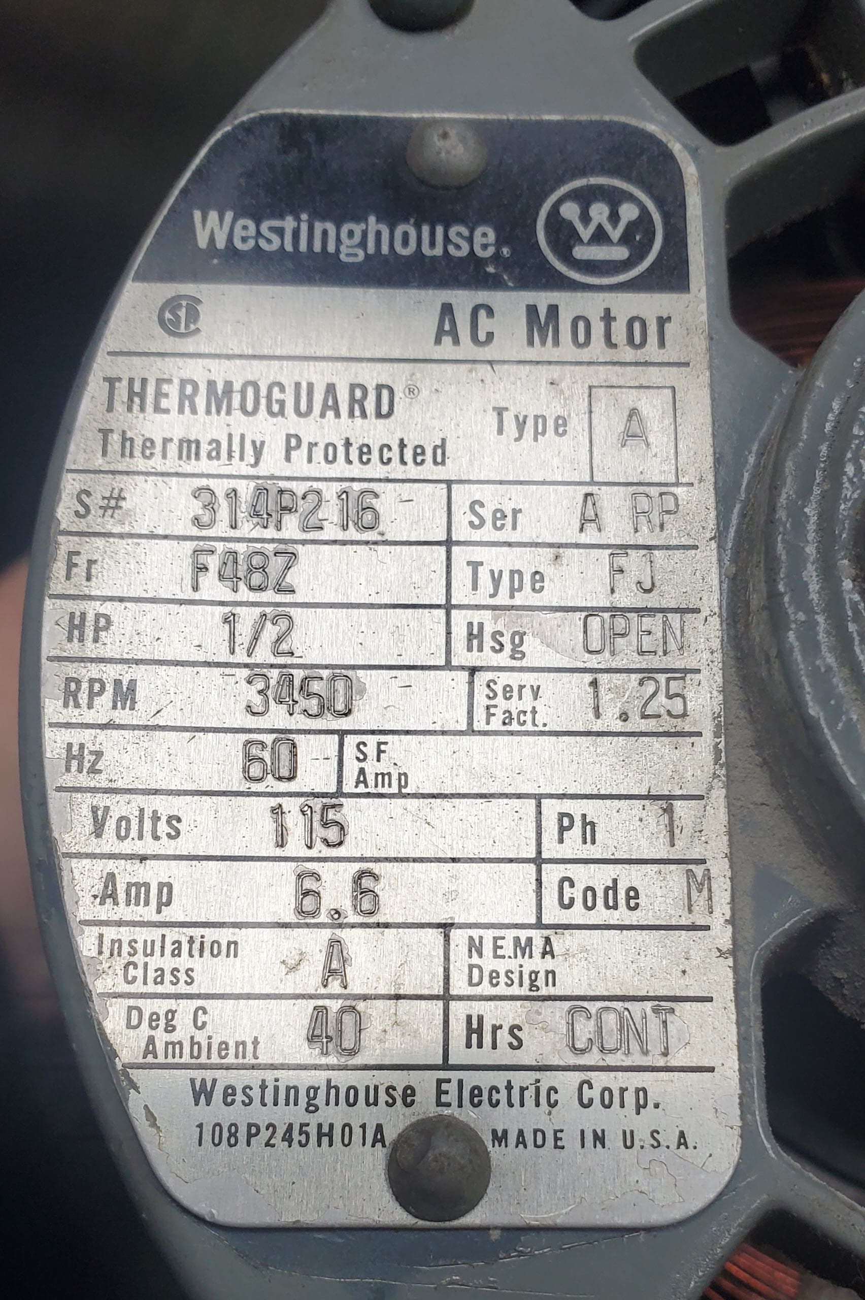
A 1725 rpm motor with a failed start circuit may often be started by spinning manually.
A 3450 rpm motor has less starting torque without the starting winding and it may not be possible to spin your motor fast enough for it to start without a working starting circuit.
Please be careful Scott.
I respect you as a professional who is active on this site.
I have given you the advice that one engineer may give another engineer from a different discipline at the water cooler in the office.
A first time obvious DIY poster may be told;
“Take it to a shop, hire an electrician.”
I am relying on you, as a fellow professional, to use caution and common sense so as to not suffer injury.
Again, please be careful.
To answer that is a challenge.
The theory of the induction motor is covered in numerous texts, probably better than I can explain it but for a specific comparison of a fractional HP such as Scott has and a shaded pole motor I will give it a try.
Back to basics.
The motor main stator winding current induces currents in the rotor squirrel cage winding.
Both the stator current and the rotor currents cause opposing magnetic fields that repel each other.
At rest, no torque is generated.
Once the motor is spinning, the inductive lag causes the rotor magnetic force to at at a different instantenous phase angle than the stator magnetic force and that angular difference results in torque to turn the motor.
The key to developing starting torque is to develop a phase shift between the stator magnetic field and the rotor magnetic field.
In a polyphase motor, each stator phase winding creates a magnetic force that interacts with the magnetic field developed in the rotor by the previously energized phase. As a result, a polyphase induction motor develops torque at a standstill.
Not so, a single phase motor.
How to create a phase offset with only one phase supply available?
Back to basics for a moment.
The current in an induction coil lags the applied voltage by an amount approaching 90 electrical degrees.
How much does the current and the magnetic field lag the applied voltage in an induction coil?
That depends on the X/R ratio. The ratio between the inductive reactance and the resistance.
In a purely resistive circuit there will be zero electrical degrees between the applied voltage and the current.
As the circuit becomes more inductive, the current lags more and more and the lag may approach 90 electrical degrees. (I say approach as an induction coil will always have some resistance.
So, different X/R ratios will result in different phase angles.
Different phase angles will result in an offset of magnetic forces that will develop starting torque.
The starting winding will typically have a higher resistance and as a result a lower X/R ratio than the main running winding.
When more starting torque is desired, a capacitor may be designed in series with the starting winding and the resulting current in the starting winding may lead the applied voltage.
What does that have to do with a shaded pole motor?
A shaded pole motor typically has salient poles.
There is a slot near one edge of each pole.
One shorted turn of heavy gauge copper wire is placed in the slot so as to surround the small part of the stator pole.
As result, that small part of the stator pole has a different effective inductive reactance and a different X/R ratio. This causes the shifted phase needed to develop starting torque.
In both the induction motor and the shaded pole motor, starting torque is developed by the use of different X/R ratios to create a phase offset and a shift in the center of the magnetic fields.
ps; “Not that the answer must be long but it will take me awhile to make it short.”
(Mark Twain?)
Long answer is fine and I am grateful for your taking so much time with this. I only found shaded pole as household examples in my Richardson textbook from 1982. This also reminded me of the primitive motors we built in HS Electronics class. I do recall that mine could ‘lock’ and hum in some cases.
It sounds like a start capacitor adds more phase difference in the start windings WRT the main ones. In the Westinghouse lookup it is a very obvious feature mounted on the motor case.
Thanks, WaRoss I promise I will be careful. Hopefully this weekend I will get some time to tear into it and I will post what I find… I will probably have even more questions once I get inside it.
Excellent. Yes indeed that motor does have a start cap. It’s under that can. A failed start cap, (very common) would result in the symptoms you’re seeing. As would a start-switch issue as Bill has described. However, cap failures are probably 3x more common.
You can lift the can to get to the capacitor.
Inspect it for leaks or bulging.
Unplug one or both and using your ohmmeter see:
If the cap is shorted.
See if it’s open.
See if it does anything cap-like by hooking the meter across the cap to see the needle climb to an eventual stop. Then reverse the meter connection and watch for an identical needle performance.
Be careful, a charged, unconnected capacitor looks harmless sitting there with no wires attached, but it can bite you! I know. My Dad ran a Shell Service Station and his workers got a kick out of tricking the 13 year old me into picking up a charged, disconnected “condenser” (capacitor) from under the distributor cap of a 1960’s car. ZAP!!! I learned two things PDQ. I could not trust those guys, and how a capacitor works.
Use insulated tools and gloves. Then you can double dog dare it to bite you!
The only thing I would add to Keith’s post is an expanded description of the Ohmmeter action.
The Ohmmeter sources a small voltage and measures the resulting current through the component under test.
That voltage will charge a capacitor and and the meter will initially indicate a short circuit.
As the capacitor charges, the current drops and the Ohmmeter reading rises.
The Ohmmeter reading will eventually stabilize close to the value of the internal discharge resistor. This is often in the order of meg-Ohms.
When the leads are reversed, the Ohmmeter discharges the cap and then charges it at the opposite polarity.
With the analogue meters of ancient history, the needle would drop below zero while the cap was discharging.
I hope that this helps you to understand the meter readings that you will see with a good cap under test.
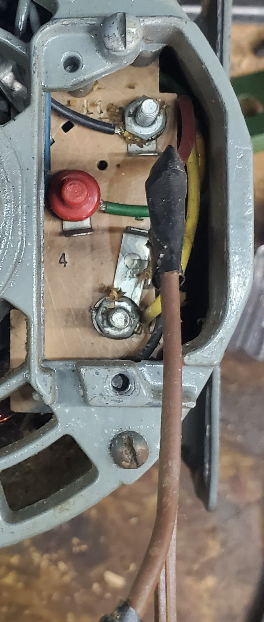
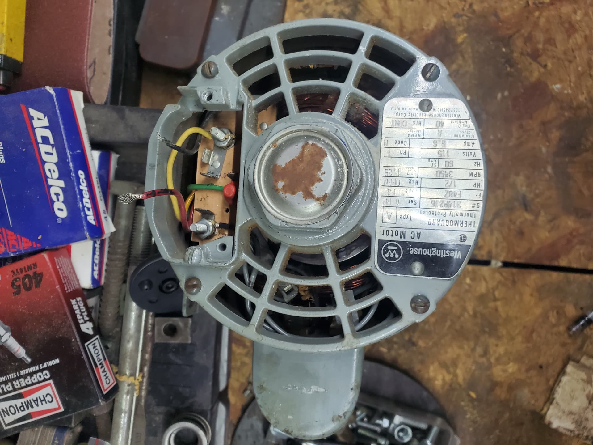
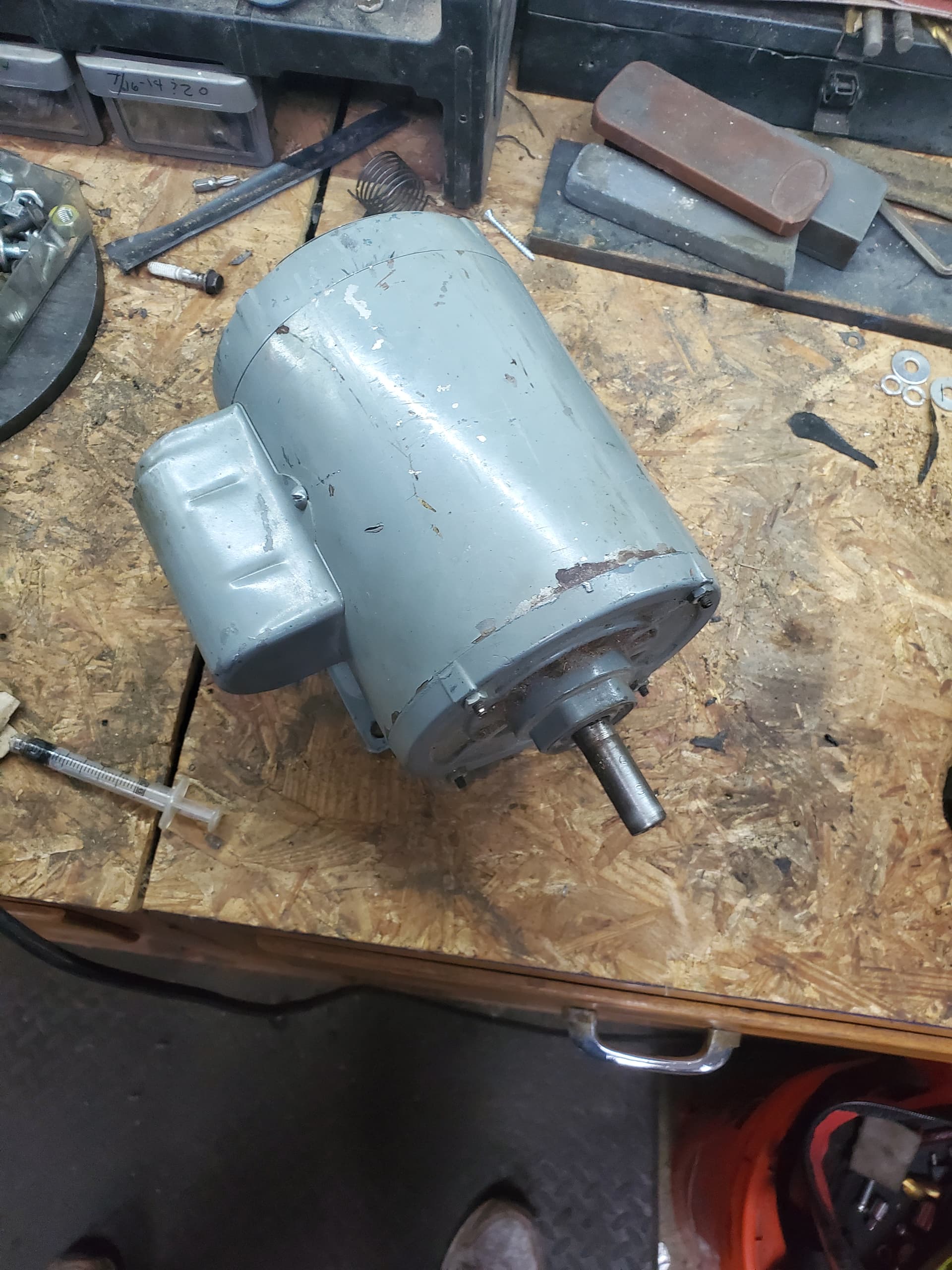
I took it apart and took some more images of it. The red & Black wire from the images above are going to (red) windings and the black is going to the back of the circuit board. I have not tested it with an ohmmeter just yet. Wanted to post these before moving forward.