That sounds good.
The present weather demonstrates the reason for the shift in terminology away from “Global Warming” towards “Climate Change”. grin
Hello Spar: I have a bucket full of caps for you.
They have all been in storage for a number of years so you may want to consider reforming them before putting them in service.
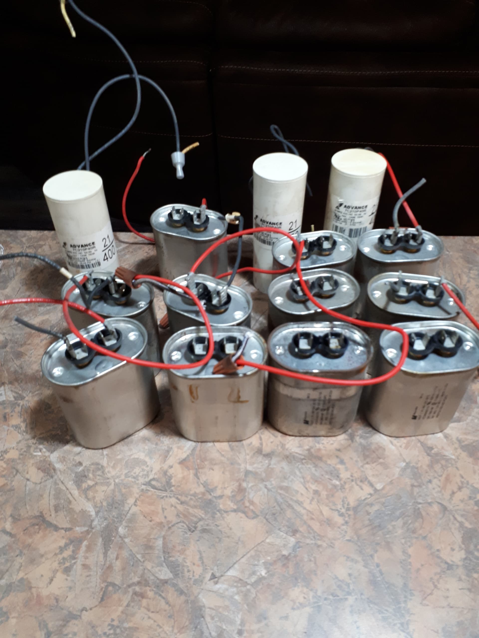
Three are 21 uFd, eleven are 24 uFd, ±3%.
All are 400 Volt, continuous rated.
I hope that this helps.
Yours
Bill
Weather looks good for this weekend.
Last night I checked that things are warming up in the shop. Planning to get the test motor into the lathe tonight. The main shaft is easy but I would like to get the rear shaft into the tailstock. Not sure if this tailstock can take the weight.
What does “reforming” capacitors mean?
Reforming capacitors:
Electrolytic caps function by means of an insulating film formed by the chemical and electrical interaction of the electrolyte and the foil plates.
If the capacitors are unused for several years, the film may break down.
If the caps are then energized with full voltage, they may explode.
The insulating films may be “reformed” by the application of a lower voltage in steps.
Once the caps have been reformed, they are good to go.
Any capacitor is subject to film breakdown if left un-energized for several years.
Brand new VF Drives that sit for several years before use, occasionally suffer exploded caps when put into use. On extremely large industrial projects, Drives may be purchased and delivered early in the construction schedule. Several years may pass before the drives are commissioned. It is a known issue that some caps may fail during commissioning.
Reforming schedule: Sorry, I don’t have a schedule to hand.
The issue was discussed several times on a site that I left when it became a troll haven.
Alternately, let’s see if It-smoked or jraef will jump in here.
Or, you may wire the caps in parallel and put them out back on the end of a long extension cord. Plug the cord in from a safe distance and see what happens.
120 Volts applied to 400 Volt rated caps may reform border-line caps, but wait to see what Keith and/or Jeff recommend.
My retirement schedule has been wide open for several years now, but I am embarking on a new venture and have a lot of clutter in me schedule.
eg: I am off to Saskatoon tomorrow for an interview. That will be 260 miles each way.
If and when the new venture materializes, I will post some details in the Pub.
There is some interesting reading here:
https://www.6v6.co.uk/vcomp/tech_tips/reform_caps.htm
1 Like
OK, thanks Bill. That article is just what I was looking for. For an AC capacitor, would you do the process polarized one way, then flip the leads and re-do the same? Or is there no advantage to doing that? Certainly not as convenient to set up a 120V DC through a rectifier as it is to just direct wire to the AC.
Good luck, wherever you’re going. I’ll fuss about with the setup this weekend. Looking at all the things I need to put together, that could take a while, so you may not be missing much, here.
It barely fits on the lathe.
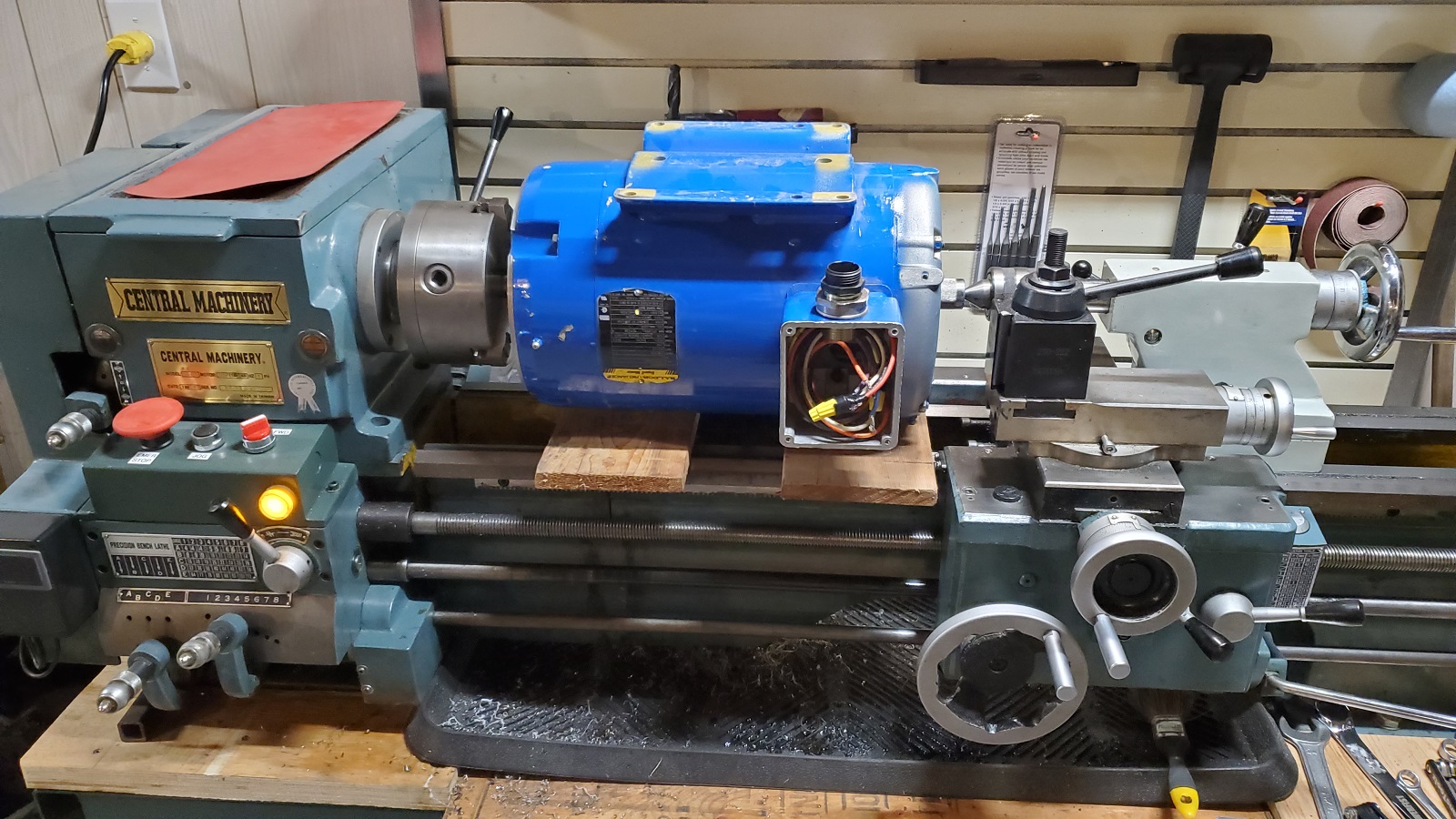
There’s enough space as long as I don’t let the baseplate whip around and strike the bedways of the lathe.
There are boards on the lathe ways to protect them until I start to run it.
BTW,
This mounting is premature because I also need to re-connect the wires to parallel-Wye so that there’s no chance of generating 480V! This is a dual-voltage motor rated at 230V/460V and it’s currently set up for 460V.
Quick update. I did some tests on the weekend, but I have a lot more to do before I get the whole picture. Some quick lessons:
With the wiring still in 460V/1200RPM, I tested 45, 270, and 315 uF capacitors. Cut-in where the capacitors start to excite the winding varies with capacitance. I can extrapolate that to get the generator to self-excite at 150 RPM, I’ll need about 600 uF capacitors.
I tested capacitors in a Delta bank. I measured voltage line-to-line, and I measured current on the lines and in the capacitors. There seem to be high circulating currents, even when there is no load.
I did make up some 30-ohm loads and connected them in Star to the output of the capacitors. This made a noticeable difference in the mechanical load driving the generator but results in only a small about of useful electrical power. In one test setup I measured the following:
1096 W Mechanical power input
1014 VA Line power
379 VA Load power
559 VA Capacitor power
So this is only 35% efficient. Of course I am probably far away from an optimal point. I’m just using materials that I have available. I’ll need to test more capacitors to know what value gives the best power output, and likewise I need to find out the ideal size of the resistor bank before I’m sure it’s able to dissipate a lot of energy.
I should add that the loads are simple resistors, so I trust that I can use “379 VA” as equivalent to “379 W” for comparison to “1069 W” mechanical power to derive the efficiency.
I can’t do that with the line load or the capacitor load; both in VA. Actually I will need to do a lot more work before I can really determine anything useful with those figures. But I measured them and I’ll keep them just in case I can, later.
Something that may be interesting to try.
If your motor is wye connected, connect the capacitors across the 480 Volt connections. T1 T2 T3.
And connect a test load across the 240 volt connection. T4-T7, T5-T8, T6-T9.
Wye connection identification:
Continuity across one group of three wires.
Continuity across three groups of two wires.
Delta connection identification:
Continuity across three groups of three wires.
It took me a while to figure out what you meant.
Now that I have it sounds very compelling!
Yes, I can try that.
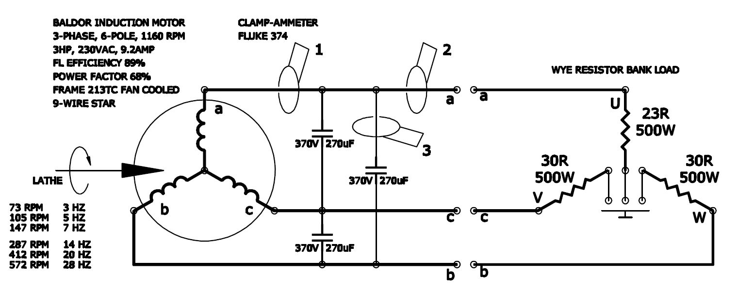
Here’s the circuit I’m trying now:
Past few weekends, had loads of fun.
So far I’ve only tested a fraction of the possible combinations I can try.
The results I first posted about were pretty far away from the optimum. I also had unbalanced phases, for no good reason, and it was really hard to make any sense of the current in the different phases.
I don’t have a way to measure power factor, yet. I only have VA to work with, not the reactive vectors. I believe this can be done with an oscilloscope.
One thing that is predictable is the frequency at which the field begins to form, which varies with the capacitor being used.
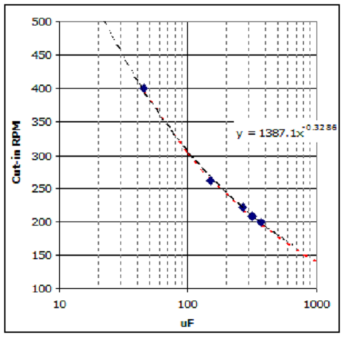
These speed ranges are too high for a 8-ft to 12-ft size of turbine that I would likely build for a generator this size. I would prefer a cut-in speed around 100 RPM, but that indicates I need about 800 uF capacitors in a Delta. I am hoping that when I re-wire the motor/generator in parallel-star that this will drop to a lower range of speeds.
Edit: I should add that I’ve noticed the cube-root power in the curve-fit above. I haven’t figured out what it means, yet. But it’s so darn close to -1/3 that it really can’t be anything else.
There is always the red-neck method of PF calculation. grin
Tools needed:
Capacitor,
Clamp on ammeter,
Drafting table.
Compass.
For the motor under test:
Connect a set of capacitors temporarily.
With the clamp-meter measure:
Line current, (Unknown phase angle)
Capacitor current, (Assume 90 degrees leading)
Motor current. (Unknown phase angle)
Pick a suitable scale and lay out and draw a vertical vector representing the capacitor current.
Set the compass to represent the line current and from the top of the vertical vector lay out and draw a suitable arc.
Set the compass to represent the motor current and from the bottom of the vertical vector lay out and draw a suitable arc.
Draw vectors from the intersection of the arcs to the top and to the bottom of the vertical vector.
Draw a horizontal line from the point of intersection of the arcs to the vertical vector.
Now you have the picture that may be worth many words.
The horizontal line represents the real current and is proportional to Watts.
The upper inclined vector represents the actual line current and is proportional to the line VA and to the corrected PF.
The lower inclined vector represents the motor current and is proportional to the motor VA and to the uncorrected PF.
You may measure your phase angles directly or you may choose to scale the values and calculate the phase angles arithmetically.
I am sure that you will find a way to adapt this method to your test setup.
Hope it helps.
Disclaimer. This method disregards the effect of any internal discharge resistor of the capacitor.
Justification:
The charge time of the capacitor is in the order of 1/4 cycle or 4 milliseconds.
The discharge resistor, if required must reduce the charge to less than 50 Volts in under 1 minute.
That is a maximum time ratio of over 14,000:1
The discharge time may be less.
Consider a discharge time of 6 seconds. The time ratio is still over 1400:1
I am willing to disregard any error introduced by ignoring the effect of the discharge capacitor.
I think I will model it in LTspice. Not sure how to get reactive current vector out of it, but that’s more a matter of not having tried before.
Shred observation.
Industrial PF correction capacitors are rated in KVAR, it makes the selection and application easier.
From the KVAR, we can calculate back and determine the impedance of the caps. This will be important later in the explanation.
The KVARs are rated at a specific voltage, generally 480 Volts.
Similar to a heater, at half voltage the Watts or KVARs are 1/4.
But this is dependant on the impedance of the capacitors.
The impedance of a capacitor is frequency related. When you double the speed, the impedance is halved. This effect will add one or two powers to the exponent.
But you have the capacitors connected to an inductive winding.
The impedance of the winding is also frequency dependant, but the relationship is not linear due to the combination of inductive reactance (frequency dependant) and resistance (not frequency dependant).
While the impedance of a capacitor drops with increasing frequency, the impedance of the induction rises with increasing frequency.
I suspect that the power of the exponent may vary with the X:R ratio of the winding from motor to motor.
I hope that this helps explain the effect that you are seeing.
Nope. Unfortunately, it went the other way.
The cut-in speed for a given capacitance doubles when using parallel-star motor connections. Where the 370uF capacitors made it cut-in at 200 RPM when the motor was wired in series-star, with parallel-star the cut-in is about 360 RPM. This is many times too high to match a set of rotor blades of a size necessary to run as a wind turbine.
I’ll keep investigating this motor configuration only as long as there’s some possibility that it might be more efficient or stable than the series-star wiring. Otherwise there won’t be much benefit. Either by handling the cut-in with extra controls (switching relay) or by more expensive capacitors, the goal is not to make the generator more expensive to use.
I may be going to Calgary sometime next week. If so, I may be able to drop off the bucket of caps on my way home.
(I may not get a chance to go home on the way to Calgary.)
Not positive but a good possibility.
If you won’t be home, I can leave the bucket in front of your shop and be on my way.
Hi Bill,
I am still staying with my parents thru next week, so the timing is bad. I’d rather be there when you drop by to at least say hello and show you the apparatus.
Let’s plan the rest by phone or e-mail, for simplicity.
I’ve continued my testing - just haven’t posted much about it lately. Still thinking about the results a lot. It’s very interesting to try out ideas.
I tried something like that yesterday. Frankly, I mis-remembered what you’d suggested, and tried putting the Capacitors across the 240 connections, and the load stayed on the T1-2-3 connections. When I started up the lathe to drive it - absolutely nothing happened. It ran like it was completely unloaded, whether the load was switched in or not. It wasn’t even like there was a capacitor load. I could measure no current any where. Shut it down, and switched the setup back to the way it was (all capacitors and loads on the 480V outputs). And still nothing happened. It had stopped working altogether!
After many hours pondering my mistake and what could have changed, I realized that I had managed to completely demagnetize the armature. Not even a whiff of remanent magnetism to start the induction cycle. This morning I connected a 12V battery across two of the output lines, held it there for 10 seconds, then started it up and Voila! Back to normal. Haha, a little lesson learned about how the self-induction cycle begins.