Use of an induction motor as generator for a wind turbine

For as long as I’ve been building wind turbines, I’ve been using permanent magnets in the generator to fabricate a rotor that is self-exciting. It drastically simplifies the electrical system by doing away with circuits to energize a field and also allows for a direct-drive between rotor blades and the generator.

I’ve recently taken an interest in the possibility to use an induction motor instead. This requires me to figure out some difficult things, because I do NOT want to use a gearbox to mate the rotor blades, which only operate in the 100-500 RPM range. I’m trying to find my way to an induction motor that will self-excite in this speed range, and yet not need 16 or 20 poles.

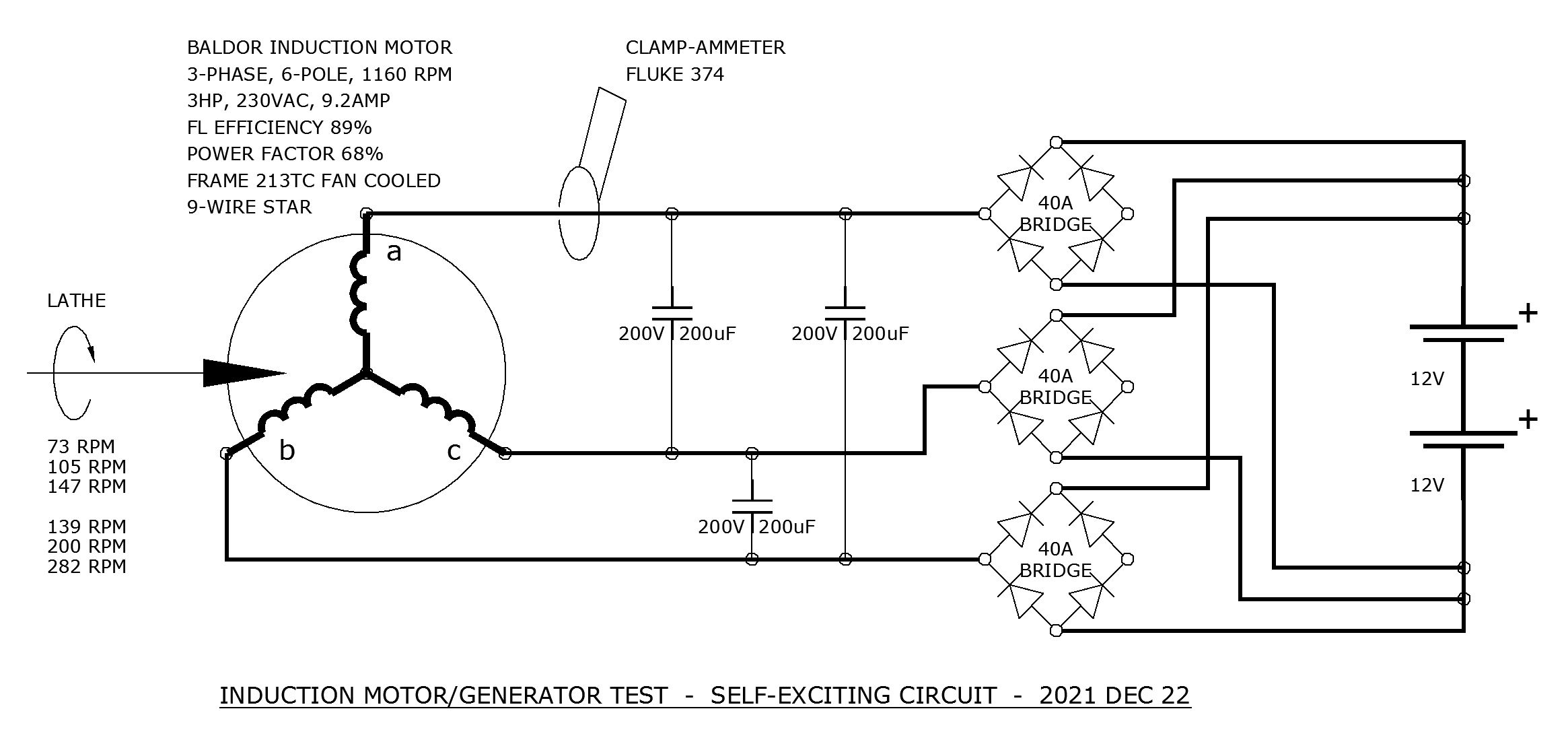
At this point, I’m still reading and doing the math so that I can understand what’s possible, reasonable, and what’s impossible. If any possibilities open, I have some stock 3-phase motors that I can do some experiments with. I also have a lathe, which can be used to drive the motor’s shaft at variable speeds to simulate operation as a generator.

I’m also keenly aware that “this has been tried before”, and by people who know much more (and much less) than me. So I humbly explore the art of the possible.

If starting with a common 4-pole 3-phase induction motor, its synchronous speed will be 1800 RPM but with slip it will normally run at about 1700 RPM. As a generator, slip reverses, so you would expect about 1900 RPM where the now-generator can produce about as much power as it could consume when it was a motor. Since the VARs are always a waste, that’s not perfectly true.

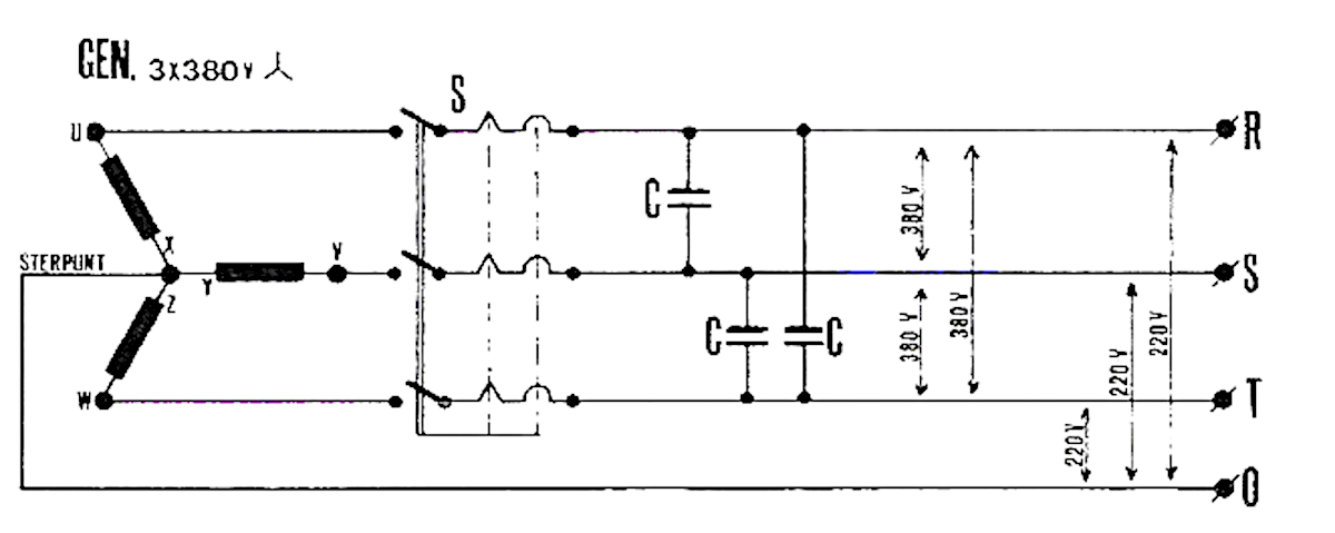
To make it generate, it can be excited by a bank of capacitors. The capacitors apply a magnetizing current that will grow large enough at the synchronous speed to stabilize the gap flux so that real power can be generated. The capacitors have to be sized correctly for this to work. The math for this is relatively straightforward, but I haven’t been finding it in common textbooks about motors. I will post some examples of tech journal papers that I have found that have informed me of the capacitor sizing math. For a common industrial 3-HP motor I expect the three capacitors to be rated about 200 uF and 300V, which is common enough though not cheap.

This is where I think my curiosity gets me into trouble. I want this induction motor to self-excite at a speed MUCH lower than 1900 RPM. More like 1/10 of that, i.e. < 200 RPM. If this is possible, this would allow direct drive of the rotor to the induction generator with no gearbox.

But so far I’m coming up with math that goes out of whack. To self-excite at lower speed (hence, lower frequency) the value of the capacitor needs to increase substantially. Using the speed ratio that I suggested above, the synchronous frequency of the generator is only 6 Hz, not 60 Hz.
That drives a capacitor value of 10^2 greater than it was before, or 20 milliFarads, still at 300V. I think the math is right, but that seems like unobtainium, to me.

Can anyone relate to this line of thinking? Any insight into how close my math is to reality?

A small bibliography:

Igbinovia Self Excited Induction Generators Performance Evaluation.pdf (164.5 KB)

Greg Weinfurtner NC8V Easy to Build and Operate Induction Generator.pdf (279.0 KB)

Ekanayake Induction Generators for Small Hydro Schemes.pdf (96.6 KB)

Raina+Malik_Wind Energy Conversion Using A Self-Excited Induction Generator.pdf (694.9 KB)

Windbouwwerk page 79.doc (164 KB)

From the paper cited above (translated from Dutch) here is the relevant diagram.

Hello SparWeb.
We sparkies always consider the V/Hz ratio at various speeds.
300 Volts at 60 Hz will be 30 Volts at 6 Hz. At that frequency, saturation will probably limit the voltage at around 35 Volts.
I have a supply of 300+ Volt capacitors that I will never use.
I’ll check the values. We should be able to parallel enough to hit 200 uF.
Can you spin a motor up with your lathe to test speed and capacitor value versus voltage?
The cost will be a couple of cups of coffee and some good conversation.
Keep reminding me, this week is hectic and my short term memory is… what were we just talking about? grin.

Bill,
You’re a crafty deal-maker.
I know you just want to come over and see my windmill spin. :laughing:

Saturation; of course - having a “duh” moment over here - thank you for clearing that up.

You rightly suspect that my system only NEEDS about 30 V to get going anyway - which fits my motor’s V/Hz ratio perfectly, and probably an underlying reason why the permanent-magnet conversions also are successful (but that’s a separate topic).

Hello again:
I have read a couple of your linked articles.
In two of them I have encountered statements that I find worrysome.
One statement is that induction generators may be paralleled without synchronizing gear.
Sure, you can do that until it goes wrong and you break a shaft, and then you can’t do it anymore.
In another paper:
A three-phase generator can be converted
into a single-phase generator, which produces
approximately 80% of the machine rating,
I have been through the calculations many times, both for generators and for transformer banks.
kW depends on the prime mover.
The limit on transformer output or generator output is in KVA.
The best KVA output ratio on a three phase to single phase conversion is 2/3, or 67% On a wye connected generator with one phase abandoned, the ratio will range from 67% for line to neutral connected loads down to 58% for line to line connected loads.
Remember that famous quote attributed to Benjamin Franklin, among others of his generation:
"You can believe everything that you read on the internet." .

Sure, I found that on the internet, but the paper says IEEE across the top, so I was going to just go along with it? Now you have me worried.

Bill I love this idea of just trying it rather than wasting time with questionable sources.

I’m going to write down a schematic of my own so that we can agree on what we are supposed to be doing, first. I’ll be back soon.

Can’t argue with that,can we.
Along those lines, I would love to see a Canadian high school textbook published before the change to the International System that presents the correct conversion from Imperial gallons to US gallons.
The first guy got it wrong and all other textbook writers copied blindly, without checking.
This is an open challenge, both to locate an old high school text with the correct conversion and second to identify the source of the error.

If several generations of Canadian educators got it wrong, I am willing to cut the IEEE some slack.
The challenge with some papers is to separate the information that was validated in the lab from the information where the writer copied the wrong source or made an unwarranted assumption.
It may easily be proven mathematically that the text books have the correct ratio. The proof is based on a false assumption.
If I wanted to waste the time, I could probably prove mathematically that the 80% figure is correct, but I would be misleading you with a false assumption.
Let’s consider a typical diesel gen-set.
100 KVA (Alternator rating)
80 kW (Prime mover capability)
0.8 PF (Industry standard convention)
Now if we convert the set to single phase the ratings become:
67 KVA (Alternator rating)
67+ kW (Prime mover capability)
1.0 PF (Non standard rating)
So, if we take 67 kW over 80 kW we get about 83%.
That should pass peer review, except that that is an expression of the load that may be presented to the prime mover, not an expression of the electrical capability of the alternator.

Hello again.
I have an idea to run past you.
I understand your reluctance to consider automotive alternators for wind turbines due to brush issues.
But the brushes are for excitation.
Is it worth considering the possibility of replacing the shaft of an automotive alternator with a non-magnetic shaft and replacing the field winding with rare earth magnets?
Has anyone done this? What are the drawbacks?

AFAIK, this has been done 100’s of times before. Auto alt’s have a lot of things going against them.
The package is hard to work with. You often have flanges and mounts in all directions.
They are designed to run at 2,000 RPM and up. Not a good speed range. I know that you mean to use the PM’s to self-excite, but the number of turns just aren’t there to get a total flux high enough without a lot of speed. Also, the bearings are crap. Sure they take a pulley torque, but that’s nothing compared to a direct drive prop for angular inertia and mass. Another point against the bearings, they only last a couple of years in a car, usually driven a few hours a day. The wind turbine runs 24/7. The revolution count is like a factor of 10, even though the WT is slower.

Separate issue:
I expect the cost of Neodymium, samarium, and other rare-earth metals will go up as the popularity of EV’s grows. This will make my technique of converting motors with magnets more expensive.

I am looking for an alternative and since my current conversion practice is to take a very robust industrial motor and convert that, I’m tempted by the possibilities of not even needing the magnets, and using the motors I have without any substantial alteration at all.

This is what I propose to test. It is the SIMPLEST method I can think of to excite the induction motor, derived from the schematics in the papers I shared above. I am keenly aware that none of those papers had any DC components at all. Since those authors had no interest in such things, they didn’t even discuss the idea. Whether the reason is because they just didn’t think of it, or because it’s impossible and stupid, I can’t tell.

It would not surprise me (not in the slightest bit) if you look at it for 7 milliseconds and say “Oh that’s what you mean - that is stupid and won’t work at all”.

If so I hope it provokes you to put pencil to paper and draw what ACTUALLY CAN be used.

Looks good.
A couple of comments:
Using full wave bridges, you have six diodes unused.
Consider six 40 Amp diodes mounted on a heat sink. (Subject as always to cost and what is on hand. There is nothing about your bridge setup that won’t work.)
A test you may want to do to determine the approximate inductive reactance of the motor.
Hook a heater or other resistive load in series with two motor leads.
Apply 120 Volts to the series combination.
Measure the current and the voltage across the motor leads.
From that, calculate the impedance across two motor leads.
Measure the DC resistance across the motor leads.
Calculate the inductive reactance.
Sample example:
Imp = 1.5 Ohms
R = .5 Ohms
1.5 x 1.5 = 2.25
.5 x .5 = .25
2.25 - .25 = 2
Root 2 = 1.414 Ohms inductive reactance.
Inductive reactance is frequency dependant so at

It has been mentioned in more than one paper that the induction generators will not start under load.
That should not be a problem.
Your setup will not see a load until the generator voltage exceeds the battery voltage. Saves a contactor.

The motor slip is 40 RPM. Lets try a base of 1200 RPM + 40 RPM slip.
That gives us about 5.2 RPM per Volt plus 40 RPM.
For 28 Volts charging we need about 185 RPM.
That’s around 8 Hz. The inductive reactance will drop to about 1.4 Ohms to around 0.187 Ohms.
Now these are not exact figures. The Impedance of a single winding may vary between 50% to 67% of measured depending on the motor being wound star or delta. The motor has 40 RPM slip at full load. I am not sure if I have dealt with that properly and 40 RPM at a base of 145 RPM is much more significant than 40 RPM at a base of 1200 RPM.
I would not call my figures a WAG taken to two decimal places.
If you call it 1/2 of an order of magnitude taken to three decimal places I can’t argue.
It is intended to give us a reasonable starting place for shop testing.
To make it more fun and to avoid you getting unpleasant surprises, the 40 RPM slip that I mentioned is at full load and varies down to zero RPM at no load. The 40 RPM represents the frequency of the induced current in the rotor and from VFD theory this induced current should be relatively independent of shaft speed.
If we keep an open mind then testing should be fun.
My rough figures and assumptions should get us in the ballpark.

Slip, or, how do you get 60 Hz when the machine speed corresponds to 62 Hz?
The induction machine depends upon slip to induce a current in the rotor.
1200 RPM corresponds to 60 Hz.
1240 corresponds to 62 Hz.
The answer is the rotor frequency.
At 40 RPM slip, the frequency of the rotor current will be 2 Hz.
A fully loaded 1760 RPM machine will have a rotor frequency of 2 Hz.
A fully loaded 1160 RPM machine will have a rotor frequency of 2 Hz.
At 50% loading the rotor frequency will be very close to 1 Hz.
If windage and bearing losses are factored in, the slip, either in RPM or Hz is very linear with loading.
Look at a motor speed/torque curve over the last 100 RPM.
That is, on a 1160 RPM motor, the curve from 1100 RPM to 1200 RPM.
Now imagine the base of the graph relabelled as slip.
That is synchronous speed minus actual speed.
So, 1200 RPM = 0 RPM slip or 0 Hz. (And zero torque).
1160 Rpm becomes 40 RPM slip or 2 Hz, and 100% torque.
1120 RPM becomes 80 RPM slip and about 200% torque.
The original graph was valid only for 60 Hz applied to that motor, or valid used to predict performance when driven overspeed to be used as an induction generator.
When that last portion of the graph is relabelled as slip, the graph becomes usable at any base speed from zero RPM up to 200% or 300% of rated RPM.
If our 1160 RPM rated example motor is used in a hoisting application, Then 2 Hz applied frequency will produce full rated torque at standstill and will hold full rated hook load stationary.
Easy to say, but more difficult to do in practice, but valid.
In actual practice, if the hook load is transposed into a percentage of rated torque on the motor, then that percentage may be used to determine the frequency that will develop a balancing torque.
I know about it. Gurus like Jeff R do it in practice.
For our use, know that that slip RPM or slip frequency will be with us at any speed.
I think that we will be safe taking the speed or frequency at which charging starts as our base speed.
eg: The speed at which the output voltage equals the battery terminal voltage will be the base speed. Then add 40 RPM for full load speed.
With this in mind, and when we get together with a truckload of capacitors, let’s verify this relationship as best we can with the available equipment.
Charging 12 Volt batteries, charging 24 Volt batteries, charging 36 Volt batteries, at the available lathe speeds .
Then, rather than theory, you will have theory validated by shop tests and shop test results explained by theory.
I have a feeling that such a presentation will be more in focus with the tone of the other fora which you frequent.

I will take your WAG and raise you a test.
Got some free time next week?
This week is going to be cold so setups on the lathe will be slow. We need a warm day for this. Lathes don’t run well cold.

Sounds good. I’ll get back to you on this.

I looked at a sample capacitor, Spar; 24 uF at 400 Volts.
Some dis-assembly required.
The capacitors are inside “take-out” discharge ballasts.
When it warms up a little I’ll start cutting ballasts open to liberate the capacitors.
Will about a dozen capacitors be enough to start with?
We will have to watch for a break in the weather.

No need any more!
Browsing Princess Auto and, would you believe it, I found some start-capacitors. Not “run” caps, but at least worth a try. I have a trio of 45 uF and a trio of 270 uF, each rated at 370V.

I’m eager to see what happens, but the weather is NOT cooperating. My un-heated shop is now cold-soaked below -20C and it will stay that way even if the outside temperature goes above freezing for a few days. I don’t see any practical opportunity to try this soon.

Note that if this test actually goes well, then the 2HP lathe could be driving up to 2HP of load. This is not something I want to do when the lathe is too cold to run well.

In the meantime, I can do some checks that these capacitors are actually in good condition. I can put together a capacitor measurement circuit with an AC 120-12V transformer, a few 10-ohm resistors, and the capacitor all in series. The current will be low but the combined resistor and capacitor will give a current that’s easy to measure, with and without the capacitor, then back-calculate the capacitance it ACTUALLY has. Yes I know about the vector math and ready to do it.

For once, a little test that went smoothly.
Putting two 10-ohm resistors and 1 capacitor in series I measured the current, then re-measured the current with the capacitor removed. The difference between the vector sums gives the impedance of the capacitor and from that I got the capacitance of each.

Labeled: 270 uF +20%/-0% — measured: 295, 290, 280
Labeled: 45 uF +10%/-10% — measured: 44, 43, 43

I don’t actually know for sure if they’re run caps or start caps. Let’s just treat them with the caution that any electronic device bought from Princess Auto deserves!

It always feels good when a test is conclusive.
Or you can measure the voltage across and the current through the capacitor, and assume that the current is 100% reactive. (As long as the caps don’t have discharge resistors.)
The conventional wisdom is that motor starting caps will overheat and fail if used continuously.
I used some of the “take-out” capacitors to replace faulty capacitors in Buddy’s capacitor excited diesel generator. They worked well.
The start caps may not be a good solution for permanent use in a wind turbine.
Load on the lathe, 2 HP.
Well, yes and no.
For proof of concept, the load will be what load you put on the generator.
The generator will start best with no load. Once the voltage builds up, you may add load.
I have a pair of 12 Volt batteries that I can loan for testing.
They would start the diesel truck at minus 20C, but not at minus 30C.
The truck now has new batteries and will start in whatever temperature.
I’m looking forward to warmer weather.

I look forward to it, too.
The break in the weather we are likely to get on Saturday probably won’t be enough to warm up my shop enough, though. And I’m still a workin’ stiff, so it will also have to wait for a weekend later in January.