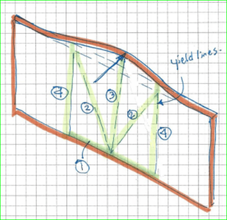
This question came up on E-T. I wanted to respond, but my computer cannot make contact with E-T. I’m not convinced that the OP came up with the appropriate yield line pattern, but I need more time to think about it and did not want to invest that time if I couldn’t communicate. Following is the yield line pattern in the E-T post.
I have not checked the yield line pattern shown on E-T, but it seems to me the sketch below is the way the plate would likely yield. It may turn out they are the same.
@BAretired I put this on E-T, “If you can upload the file to a different website, that points to problems on this website. If you cannot, that points to problems with your PC/browser. Can you test that? And let us know.“
Since you can easily upload your files to SimpliEngineering, doesn’t that tell us it’s E-T’s issue and not yours?
The graphic files that I loaded to SimpliEngineering were PNG files taken by a Snipping Tool and stored in a file separate from E-T.
I don’t believe that tells us it’s an E-T issue as opposed to mine. Others are telling me they are able to upload files to their posts, so that tells me that my problem is unique.
Actually, there is one E-T member who has experienced the same problem as mine. He attributes it to installing LibreOffice, which he did to assist me in resolving another problem. I too have installed LibreOffice and strongly suspect it is the source of the current problem.
I could uninstall LibreOffice but I hesitate to do so because I like the program in many other ways. Nevertheless, I may well do that in the next few days.
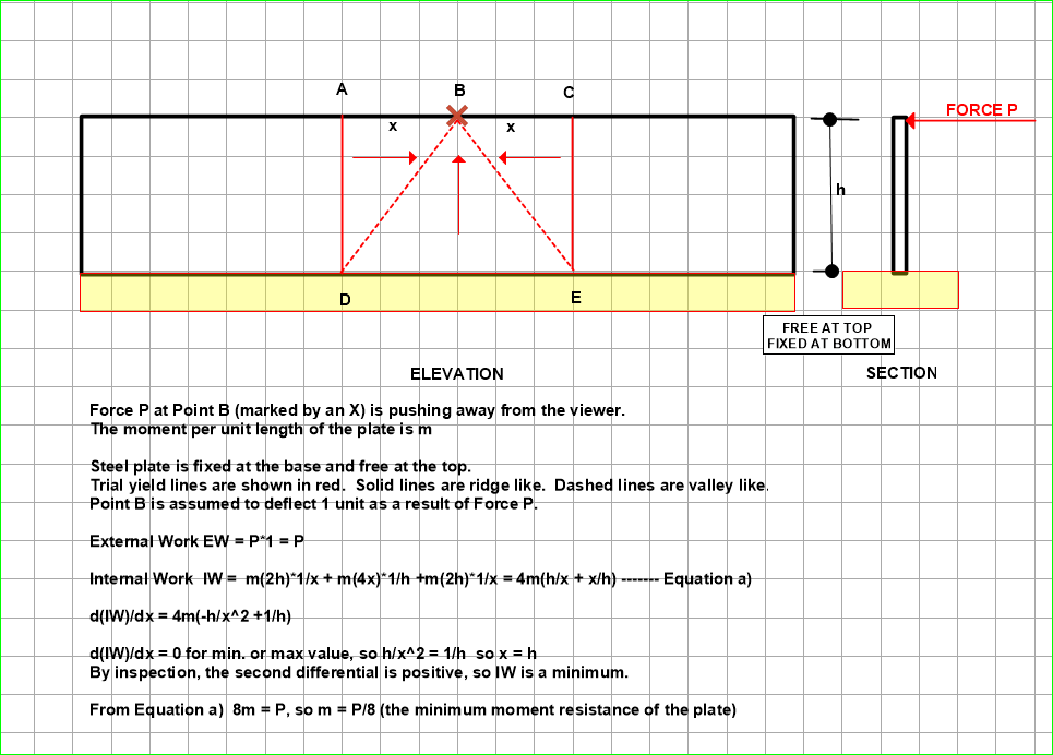
The above is similar to the pattern selected by CANPRO on Eng Tips except that yield lines #1 and #4 are not used. This is the best selection to date and I doubt that there will be any better choices because this is probably the simplest pattern available.
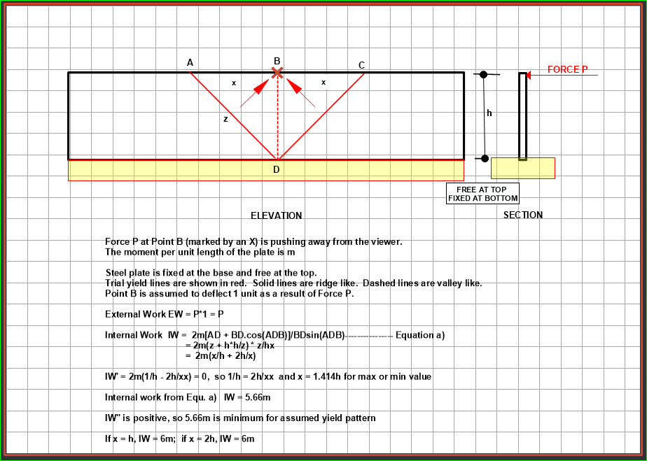
The ultimate Force, P applied to the top of the plate turns out to be 5.66m where m is the factored bending capacity of the plate per unit length, normally taken as phiZFy or phi.Fy.t^2/4 where t is plate thickness. Dimension b is not included as it is one unit, consistent with the units selected in the problem.
Interestingly, the dimension x turns out to be 2^0.5h or 1.414h instead of h, but the error in assuming x = h is not large.
Incredible dialogue… I’ve always used h on either side of the load area, never questioning the reason. Just seemed reasonable, and I’ve always used the plastic section Z.
That seems to be a fairly safe assumption, dik. If you assume an effective width of 2h and a load of P, the moment m per unit length of plate is P*h/2h= P/2 which is much more conservative than the yield line pattern would indicate.
 Can you test that? And let us know.“