Converting an induction motor to a permanent magnet generator.
An effective Permanent Magnet Generator may be DIY constructed by replacing the rotor with a new, smaller rotor with permanent magnets fastened around the circumference.
Some designs that I have seen have left me concerned with the average air gap.
If the average air gap is doubled, then the speed needed for the same output is doubled.
Is it feasible to machine or grind an arc on the permanent magnets so as to reduce the average air gap?
Is it feasible to deliberately construct the rotor with a large air gap and then fabricate arced iron pole pieces to mount over the magnets and so reduce the average air gap?
If it can be done, is it worth doing?
Does anyone have wind turbine experience who is willing to comment on the practical aspect of developing a given output at a reduced speed?
Comments and discussion please?
Would it work to machine slots in the existing rotor for the magnets? I would think it might be easier to keep tighter air gaps that way. No experience with wind turbines or generators unfortunately, so I might be missing something…
Hold that thought Makesparks. That will be one of my followup questions along with optimum spacing in relation to the number of poles.
Hi Bill,
You must have known I’d chime in.
Cutting/grinding magnets is messy, hard, and risks de-magnetizing them with overheating. I would not recommend doing that. I have actually tried cutting a NEO magnet but it took two hacksaw blades to get through it.
I got great results from magnets bonded to a rotor with flat faces machined for each magnet position. By using many small magnets the average air gap is quite small. You’re still right, the stator’s teeth have faces making an arc passing over the middle of the magnet face. There is a greater distance than the edges of the magnet which need some clearance. So this approach is not perfect. Making an iron cap for the pole sounds like it would work and it would close the gap. Could it also introduce some (“reluctance?” - weak terminology here - help please) cause additional heating of the rotor from back-EMF?
I’ve spent plenty of time on Fieldlines.com sharing ideas with other wind turbine builders. Most of them don’t get too fancy with their machines. So there aren’t too many ideas on this point that I’d like to try.
That said, I did have this conversation recently:
https://www.fieldlines.com/index.php/topic,150022.0.html
Hi Steven.
Good to hear from you.
As to the magnetic effect of the pole caps:
Your magnetic circuit has several components. The magnets, the iron core including the return path for the flux and the air gap.
They can be in any order.
The magnets, permanent or electro, supply the magnetizing force.
Similar to resistance in an electric curcuit, length matters.
One metric for electro magnets is Amp-turns per inch of magnetic circuit, based on the permeability of the iron core.
Make the iron path twice as long and the force is cut in half.
Nowcomes the air gap. The permeability ration between air and good magnetic iron is around 50,000 to 1. That’s why I fixate reducing the air gap.
An anecdote to illustrate the arrangement of the components in a magnetic circuit.
The first magnetic clapper type contactors had a habit of sticking due to residual magnetism.
The first solution was a small brass rivet or pin in the pole face that prevented the movable clapper from contacting the electro-magnet.
That worked until repeated operations beat the rivet flat and the contactor would start to stick. Replace the rivet and good to go until the next time.
Actually, as old as I am, I’m not that old.
I had some very old text books.
Then the eureka moment.
The air gap reduced the force of the residual magnetism by lengthening the magnetic path but it didn’t have to be between the movable clapper and the stationary magnet to do so.
An air gap anywhere in the magnetic circuit would give the same reduction of the force.
If you disassemble a modern contactor you will see somewhere on the back the air gap. It is actually a piece of non-magnetic material, that gives the same result as air.
It is positioned so that it does not experience any impact from the closing of the contactor.
The point is that pole caps of good magnetic material should not affect the performance, UNLESS, the is a negative effect to mounting the magnets lower to make room to mount pole pieces.
In some designs lowering the magnets may restrict the return path of the flux.
I wonder if we could prod @electricpete to do some calculations on the loss of flat poles versus radiused poles?
He likes calculating and the more the merrier on the site.
Hi again Steven;
I haven’t had time to go over your link in detail but I noticed some objection to using original rotors due to the squirrel cage, that is the shorted aluminum bars.
Most of the effect may be avoided by cutting the ring off of one end.
The bars will no lomger be shorted and will now have the same effect as would air holes through the rotor.
That’s partly my experience, too.
I made one motor conversion without cutting through the ends of the rotor, and boy did it suck. That may have played a role that I didn’t consider before.
If you keep looking at my projects, you’ll see that I often avoided the issue by machining a new rotor from solid steel round stock.
Is Electricpete here on Simpli?
WaRoss,
Hi again,
I haven’t forgotten about this topic, just needed some time to think and get back to it. This snowy weekend has given me an opportunity to look at pole-shoes again and even do a bit of sketching to visualize what might be done.
I should start at the beginning. I’ve converted a number of induction motors into synchronous generators by either machining down the rotors or (if the break apart in the process) replacing the rotor entirely with a solid steel and mounting permanent magnets on it. Here is an example of my most successful try at that, which has been running in a wind turbine for 9-10 years:
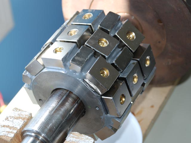
When that was inserted in the stator, of course there are huge air gaps. I’ve always wanted to reduce the gaps but how to do it with flat-faced magnets??
I’ve wanted to investigate pole-shoes for a while, and the other idea linked to above was just another impetus to try various combinations.
I’ll post some of the ideas I’m trying below in a following post. Here are the issues I have to resolve for any one idea to succeed:
1- manufacturability
2- air-gap flux
3- flux short-circuits
4- pole cogging
5- resistance to vibration/thermal cycling
I have some ideas that are OK for some issues, but no idea really seems to get all of them.
Here are some pretty pictures.
This is generated from FEMM (Finite Element Magnetic Modeling) a free-ware program that can quickly generate simulations of magnetic circuits.
The first thing I tried was pretty stupid.
I wanted to see if I could completely encapsulate the magnet in a rotor. Unfortunately all of these ideas led to a horrible amount of flux short-circuits. Let’s look at this, laugh, and move along quickly to better things…
Next, I separated the pole shoes from the rest. I knew as soon as I did it that making this work just got harder. The shoes have to be fastened somehow. The shoe alone helps a lot, and adding features that allow a kind of cleat to secure the show is also possible. But then I tried to imagine just making those shapes, and it stopped making sense.
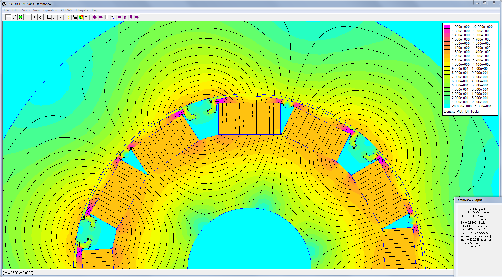
Now I’m looking at something more like a Halbach array, turning the magnets sideways and facing them together to make the pole really want to exit the outer face. I’m getting perhaps the best result from this. Both manufacturability and effectiveness seem to be OK. I just have to make a bunch of wedges. A screw could hold each wedge onto the central ring. The ring can be aluminum so that no flux short-circuits through it.
The rotor length is about 5 inches. I could build 5 pancakes each 1" thick and then slide them onto the rotor. This procedure may allow each ring to be “clocked” to add up to a helical skew of the poles. This would eliminate a lot of pole-cogging.

It may be worth explaining:
I haven’t tried to model the stator teeth because:
a) it simplifies the model (20,000 mesh nodes versus 1 million)
b) this is a comparative check, not looking for absolute value of air gap flux (yet).
c) I am lazy.
FEMM allows me to sample values from the model, and I can draw a line across the model to compute total flux passing through an area, if I want. At this point I’m just looking for an effective arrangement that I can actually fabricate, before trying to optimize.
Think of the air gap as a linear resistor.
Think of the iron as a linear resistor.
The path that your flux takes will be so many inches of iron and so many inches of air.
An inch of air equals about 50,000 inches of iron so you can ignore the iron for ballpark calculations.
Two important things about air gaps.
- The wider the air gap, the less flux density.
- If the poles are too close together, the flux will bridge from pole to pole without going through the stator.
A suggested design:
Find a piece of pipe with a diameter close to the inner diameter of the stator.
Cut the pipe in strips the width that you wish to make your poles.
Make four rings to fit on the shaft that will support the strips of pipe as close as you want to the stator.
Two rings will be of steel or iron.
Two rings will be of a non magnetic metal.
Mount the rings on the shaft so that the magnetic rings are outermost and the non magnetic rings are inboard slightly.
Mount your pole strips so that each strip is supported and fastened at one end to the magnetic ring and supported and fastened at the other end by the inner non-magnetic ring.
Place your magnets inside the strips.
Fill in the small air gaps caused by the curvature of the pipe strips with a mixture of iron filings and adhesive.
Machine an pipe or tube to join the inner ends of the magnets together.
A quick summary of air gaps.
Make the gaps as small as possible where you want the flux to flow.
Make the gaps as wide as possible where you don’t want the flux to flow.
Got it. Thank Bill.
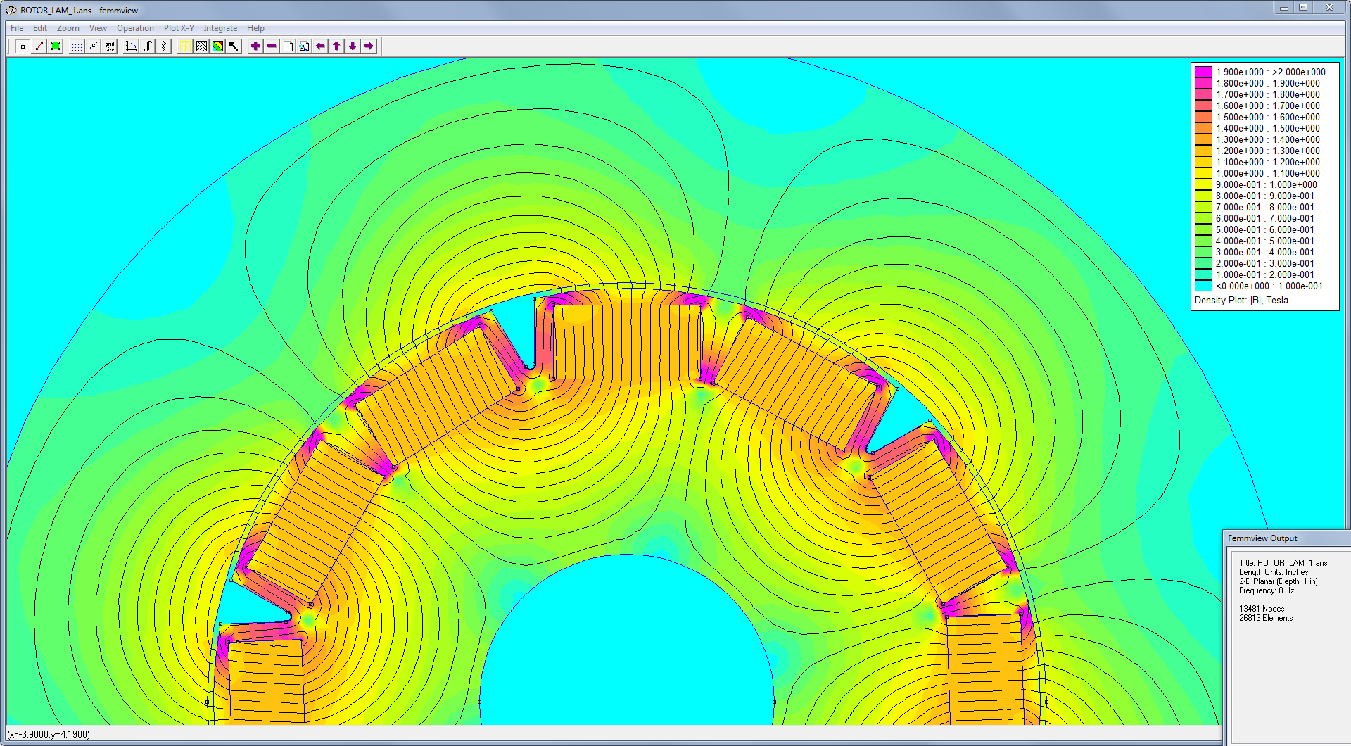
Now putting that to use. Here are two models in FEMM.
Sorry if you’re not keen on doing computer simulations. It is the only tool I currently have to predict flux density in the air gap. I do prefer “back of the envelope” calculations to work stuff out but in the 101 times I’ve asked on SE and Eng-Tips I have not been given any useful book recommendations that would help with this. Sure, Rosenberg’s bible is suggested every time. It’s not an analytical book however. I will ask again. “If you know of any book or textbook that sheds light on analytical methods to predict air gap flux in electric motors, please let me know”.
Here’s the simple motor conversion with no pole shoes.

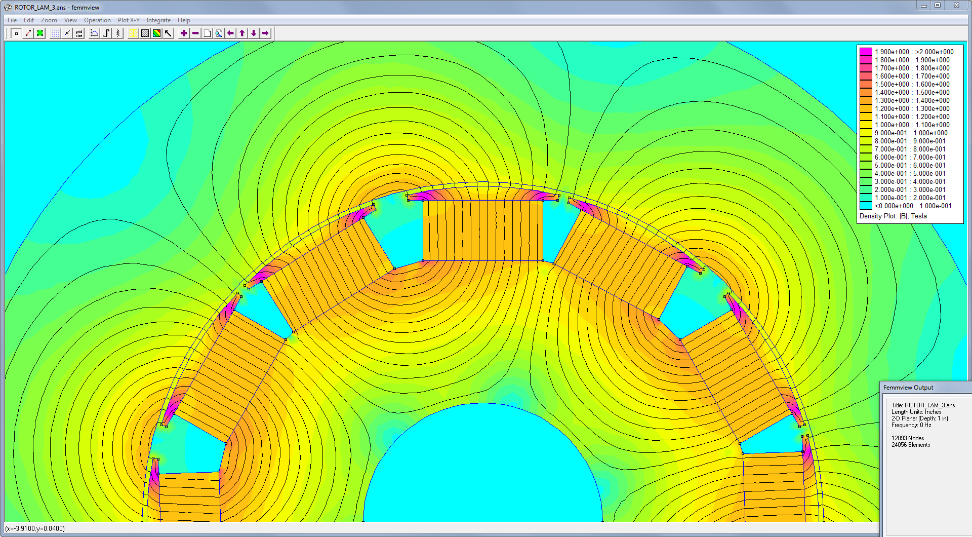
Here’s the modifed motor conversion with pole shoes, fabricated as you suggested, Bill. Started with 5" sched 40 pipe, sliced in 6 arcs, and machined 2 flats on the inside.

In each model, I can determine the flux across each pole by drawing a line through the gap, and selecting the integral function from the menu. The box in the lower right gives the answer in Webers.
Results:
Without pole shoes: 0.00141 Webers
With pole shoes: 0.00138 Webers
Hmmm… Not a big effect. Slight disadvantage to the pole shoes so far.
Can you see anything wrong with the comparison?
Please take this as a suggestion, not an authoritative answer.
I am not surprised by the answer. Where the advantage will be gained is that the arced poles will allow the air gap to be shortened further.
I appears that you have two adjacent poles. eg: N:N, S:S.
It may be advantageous to bridge them into one pole.
In my second year I studied magnetism and motors. I was prepared to estimate the HP of a DC motor from the physical dimensions for a challenge exam.
The problem was not on the exam.
I never did motors again.
I did some calculations a couple of times for electro-magnets.
I was working with electro magnets with no air gap in the magnetic circuit…
any air gap introduced into the calculations markedly reduced the calculated pull of the magnet.
Some basics:
I used the formula. MMF Magneto Motive Force equals Amp turns per inch of magnetic circuit.
Air gaps were multiplied by 50,000 to normalize with iron.
Not surprisingly, the air gap often predominated the calculations.
Hence my concern with air gaps.
What is the advantage of smaller air gaps and the resulting higher flux density?
Less RPM for a given induced voltage.
I hope that @Skogsgurra takes a look at this thread. He knows more about this than I ever will.
Got it now.
The trick is that the magnets drive the field, but they can be anywhere in the circuit. Thinking in terms of the “magnet circuit” is all I needed to realize that they don’t have to point at the stator teeth, and helped me understand some of the rotor diagrams that I was looking at on other websites. They didn’t always point the magnets at the stator and some looked a lot like this (below). Finally the coin dropped.

Hi Spar.
Please forgive me for the information on air gaps.
In my defense, it was a very long time ago and I was calculating electromagnets.
I did not realize that permanent magnets were part of the air gap.
As such, the air gap is much less critical than for an electro-magnet.
By the way, I would not worry too much about eddy currents in the rotor.
Any eddy currents will tend to stabilize the rotor.
Some synchronous alternators have solid pole pieces.
Many synchronous motors have squirrel cage windings for starting and to stabilize the speed when running.
Eddy currents, if they occur, may be your friend.
To that end, you may drill holes through the rotor and bolt it to hold the laminations together while cutting the slots for the magnets.
The squirrel cage winding may do a good job of holding the laminations together.
You can probably leave the bolts in place.
I like your latest drawing but I see a couple of possible challenges.
One; It looks as if you have told your program that the center is non-magnetic.
If the center is magnetic, it will bypass much of your flux.
Constructability may be a challenge.
What do you see as the drawbacks of automotive alternators?
I see a lot of advantages.
They are long lasting and rugged.
Driving down the highway on a freight truck on a rainy day for year after year is an indication that they will survive high humidity with only basic shielding.
You are familiar with the great weight and size advantage gained by 400 Hz as opposed to 60 Hz.
A fast spinning alternator is sending a lot more than 60 Hz to the rectifier bank.
Voltage? A fast spinning alternator will develop 100 Volts or more.
Are you familiar with load dump?
When there are a lot of lights on in a vehicle the voltage regulator is sending a lot of current through the field to keep the voltage up. If a large load, such as all the lights on a vehicle are suddenly turned off, the voltage may spike to 100 Volts before the field strength decays.
When gas was cheap, there were conversion kits to use the alternator in a pickup to generate enough voltage to drive power tools. The drawback was that the engine had to be running quite fast and the popularity of these kits went down as the price of gas went up.
So, a 60 Amp alternator developing 100 Volts, that’s 6 kW.
100 Amp and 120 Amp alternators are becoming more common. 10kW and 12 kW respectively.
The current drain for the field is a very small percentage of the output.
Some older voltage regulators may be fed by a resistive voltage divider and fooled into regulating at a higher voltage.
That’s the upside. What’s the downside?
Hi Bill,
that’s a lot of questions and suggestions. I’ll work my way through one by one.
I’ve recently learned a few things about the air gaps myself, but I’m still working on a better understanding of the effects that the stator currents will have on the rotor (back EMF). I would expect that current in the wire will apply a back field onto the rotor, and the eddies induced by that would have a heating and power loss effect. Maybe that’s small, maybe it’s even small if the rotor is a solid.
If solid parts are safe to use everywhere on the rotor, then that simplifies manufacturing to some extent. It would be simple to just have 6 long screws to hold the pole shoes down. But if heating really isn’t a problem at all, then it’s even easier to just bond all of these pieces together with aerospace structural adhesives.
At the center you’re right. I have specified that the central shaft is steel, around it is a thick aluminum tube, and then on that are the magnets and steel wedge pieces. Using aluminum prevents short-circuit flux, although some does still get through.
I am still concerned about ease of construction. Using solid pieces is a step in the right direction.
Something to be noted, which is not trivial and driving some of my design decisions. Permanent magnets will cause some degree of cogging. The tooth-to-tooth attraction will be reduced somewhat by the smooth arc segment poles I have, but I still expect some. As an additional measure to combat cogging, keep in mind that I will not be building this rotor as one whole piece. It will have layers. 4 or 5 pancakes, so to speak. Each layer will be about 1" thick, and each layer will be turned relative to the ones beside it. If the first layer has a pole pointed at 12 o’clock, then the one beside it will point its pole at 12:01. The next at 12:02. The whole rotor will not have any one pole pointed directly at any particular stator tooth, yet the poles will be close enough together to work in unison as they pass each pole in the windings. The exact angle is determined by the number of pancakes I need so that the group of them add up to a “net-zero” torque passing each pole.