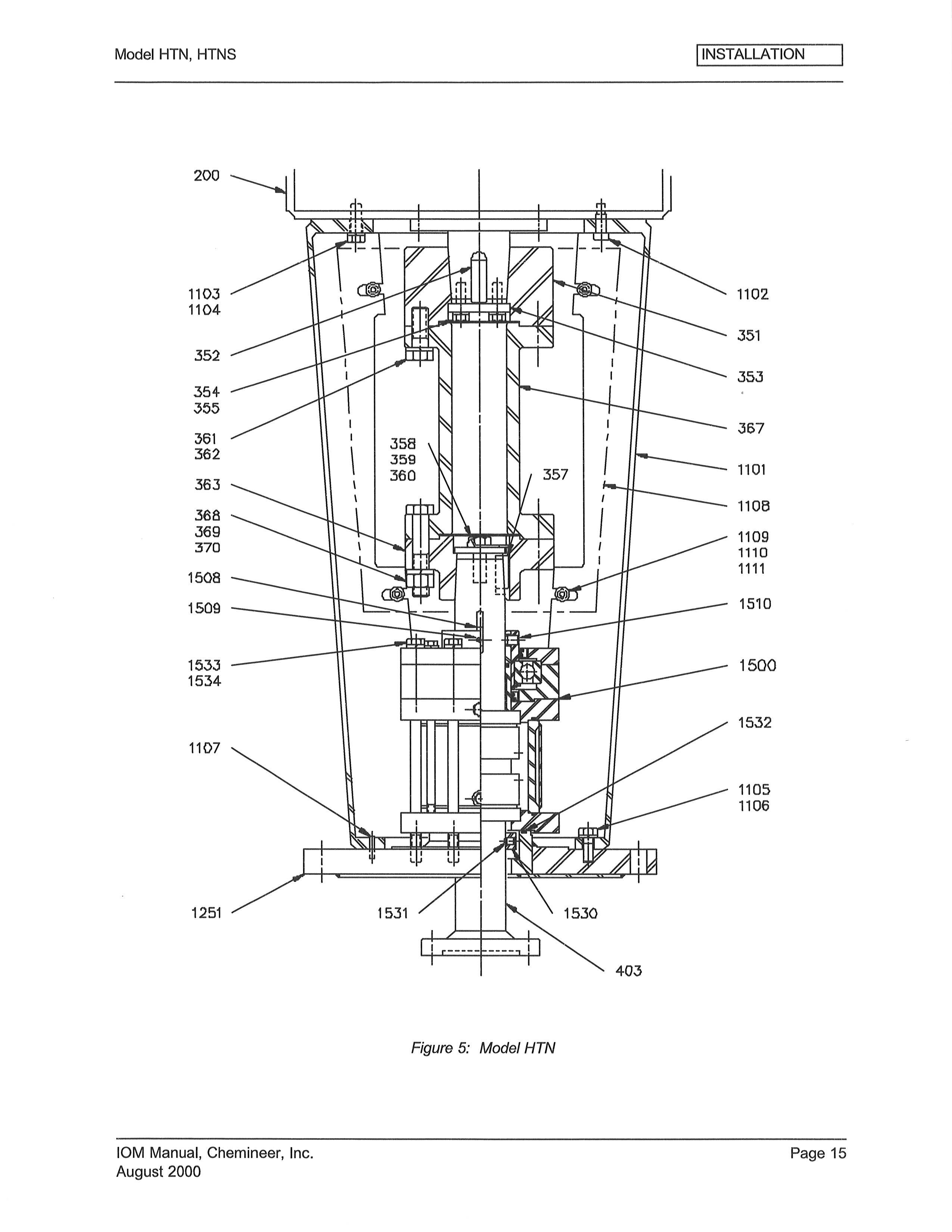
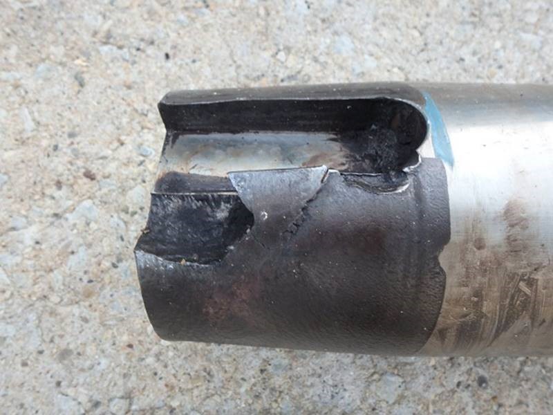
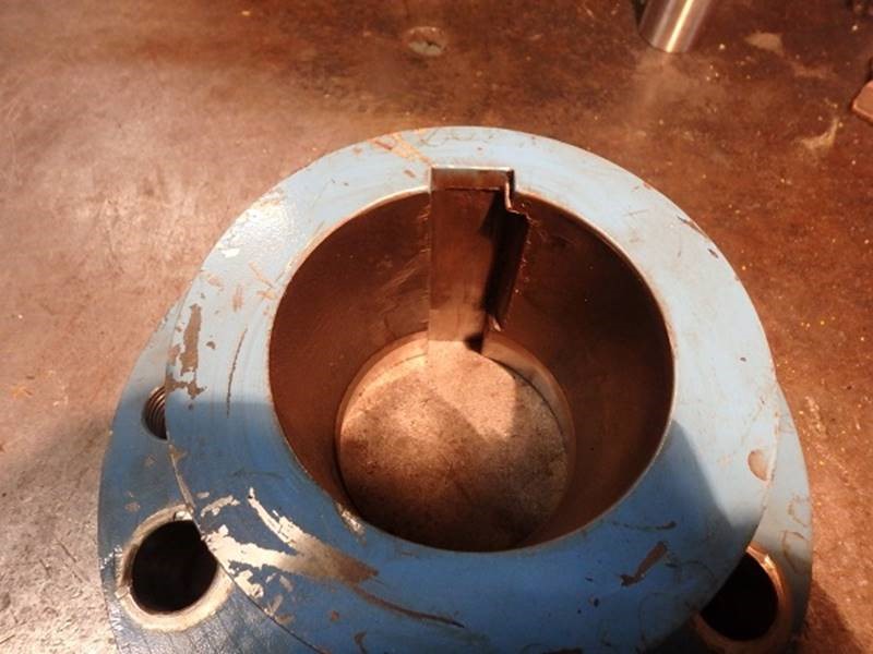
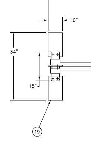
1-2 weeks ago a wobbly agitator shaft was spotted on a polymerisation reactor through the top head sight-glass. The damage was found to be a damaged drive shaft [403] and keyway in the bottom half of the coupling [363].
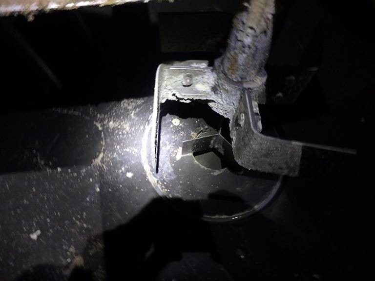
An investigation could not find a recent incident that directly caused the damage, so it must have developed slowly after the mechanical seals were repaired two years ago. Also, during the investigation, the bottom Chemineer S-4 impeller (tickler turbine) was found damaged.
By looking at past pictures taken through the top head sight-glass, it was determined this impeller was damaged 1.5-2 years ago, or within six months after the mechanical seal repair. It was hypothesised that during an abnormal batch, the agitator was turned on while only the bottom S-4 impeller was sitting in sludge/solids. So, the full 60 hp was concentrated into the bottom impeller, the shaft wound up like a spring, when the impellers bent approximately 90 degrees, the spring un-sprung suddenly sending a shock wave up the shaft, knocking the coupling loose from the friction fit taper bore joint. Then, over time it wallowed and wore away.
Now, for my question. We’d like to test this hypothesis. Is 60 hp enough to bend the four 1/4" thick 316SS plates of the S-4 impeller? Is that calculable? What equations apply? References?
The only thing I find strange about your incident is that such obvious damage to the turbine could go unnoticed for two years. I do not see evidence of wallowing or fretting. It appears to be due to one, or a number, of heavy impacts. There are only two scenarios for this failure. The turbine was stuck when started or the turbine was at speed when struck by a large chunk. I really see little point in doing any detailed calculations.
The length of blade compared to its thickness is the relevant factor. Those are “thin” blades.
Thanks compositepro! I was surprised it went unnoticed too. Until I brought it to the plants attention Tuesday at the root cause investigation, they thought it was normal. I told them the S in S-4 meant “straight blade”, not swastika.
I agree on the calculations, but, you know how these things work, my name is beside the action item the Plant Manager put down, so I gotta do it, if possible. Maybe an ME will help me out.
@Latexman - This problem is a nice mix of mechanical, electrical, with touch of structural - which is the combination of fields that happened to be my major in college (still a Life Member of ASME).
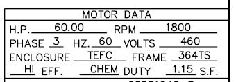
You probably have a four-pole (1800 RPM), 3-phase AC, squirrel-cage induction motor driving an 84 RPM shaft through an (approximately) 21:1 gear reduction. With an electric motor horsepower is really not that important, it’s torque that counts. Agree with you that damage probably happened on start-up; so the motor’s locked-rotor torque is the value needed. From the web, found a typical (Frame 364TS) general purpose Baldor (Reliance, now ABB) 60 HP motor, Model EM2547T ,with locked-rotor torque of 314 ft-lb. Assuming gear reduction efficiency of 70% this works out to 4700 ft-lb torque that can be delivered to the blades on start-up.
Looking at force needed to cause 4 blades to yield simultaneously (by bending as cantilevered beams), then calculating torque needed to make that happen, I get 2260 ft-lb.
Bottom line… yes, the motor/ gear reduction has the torque available (4700 ft-lb) needed to cause all 4 blades to yield simultaneously (2260 ft-lb). The calcs are fairly straight forward, just an out of the ordinary combination of engineering disciplines. Summary of my assumptions and calcs are attached. Blade Failure.pdf (270.4 KB)
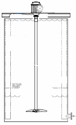
I’m assuming the tank/agitator is similar to the process holding tanks we used for underflow from coal flue gas desulfurization (scrubber) clarifiers. The agitator blades are at the bottom of a long vertical shaft so that if a large “lump” in the slurry is hit by moving blades, the entire shaft/blades just “wobble” around it.
It looks like from the photos, that the keyway has been taking some repetitive hits, with failure on one side and deformation on the other, indicating stress reversals in the shaft. Probably a bit of loose machining.
Yowza!
When I saw that picture of the blades in the beginning, I though “Huh, that’s a weird blade shape, what would be the benefit of that?”. Then I continued reading the post, detailing the damage. I am with @compositepro that I am shocked this damage occurred and the agitator kept operating for so long without notice. Is there no filtration on this unit to have caught the (what looks to be pretty large) metal fragments?