If that’s a linear position transducer like I’ve seen used in other places, then that gives a 12-bit resolution measured on a fairly short distance. I take it the transducer wouldn’t have to be in contact with the gantry for the whole stroke, otherwise:
(a) the linear actuator would have to be several feet long and
(b) when displaced to zero the rod would stick out as much off the back
Perhaps just a sensitive touch is all that’s needed, and once both sensors are contacted, the two motors could move slowly to a position that correspond with each other’s reference.
I believe the equivalent to this is normally done now with encoder wheels attached to the servo/stepper motors. A step to calibrate at the beginning of the day’s work, so that as long as the unit is powered up, the computer control knows both motors are in synchronized positions based on the encoder positions.
This is my current understanding of closed-loop operation of these machines. Which may be too simple. I have not yet read enough about the Mach3 CNC program details to understand if this is anything like how it works, or supports other kinds of gradient sensors, although I’m sure limit stops are definitely there. The encoders are handled by the motor driver, which seems to be a common thing.
The point, of course, is to learn all these details.
Yes, I am adding these “needful things” into the budget as I go. I also have to get the whole spindle drivetrain sorted out, from the motor to the collett and the essential tools, like a touch-probe.
I was thinking more like the linear encoders used for digital readouts on milling machines, they can be etched glass or magnetic types (the latter being similar to the encoders used for digital calipers). If you find the right shop, you can get them in nearly unlimited lengths, though shipping might be tricky.
The magnetic type up to 12 meters at lower resolution (still better than .001" per meter) (see page 48-53). Mitutoyo brand is good, but spendy - there are cheaper knockoffs for about 1/3 the price if you shop around. I bought the cheap ones for my mini-mill, and they work pretty well as long as I unplug the shop keg fridge when working (compressor cycling on the same circuit causes wired power supply for the DRO to drop out). If you contact some of the el cheapo brand Amazon/ebay sellers with the actual lengths you need, they can quote longer lengths than what you find on their offering pages.
I put together a stick-figure FEA model over the past few days. Really the model is simple, but pulling the numbers in and out of the solver (and checking that I did it right) takes time. Interesting results.
The gantry is an inverted “U” which must resist moments when in operation. The legs of the “U” are supported by the linear guides. These require arms that stick out forward and back. There are points where load is applied at the motor(s). The arch is made with 4x4 square tubing, the end beams are 1/4" plate.
My FEA model asks what happens when the motors on either side of the gantry get out of sync with each other. Later I will look at cutting forces from the spindle on the gantry. Will need to add elements to represent the spindle when it cuts.
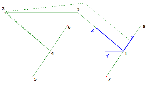
This is an ancient (1990’s!) stick-figure FEA package that is free but unsupported called GRAPE:
Linear guides at Nodes 5,6,7,8 are constrained in Y and Z, free in X and all rotations.
The locked motor is at Node 4, preventing only X motion
The applied force is at Node 1. I used a “unit” force of 1 pound to “see what happens”.
The displacement (dotted frame) in the figure is an exaggerated scale. The deflection at Node 1 is 0.00048 inch (1/2 thousandth of an inch). To go 0.001" (1 thousandth of an inch) of skew, the asymmetric load would have to be 2.1 pounds.
Interestingly, and somewhat coincidentally, I am expecting that a 200-step stepper motor with a 5:1 gearbox and a 1.5" rack and pinion drive would advance 0.00075" per step, which is very similar to the skew from the 1 to 2 pound asymmetric load.
Not surprisingly, it takes A LOT OF material to make this kind of structure much stiffer. The 4" square structural tubing is pretty beefy as it is. It’s good to have some dimensions and resulting loads/deflections worked out from an example like this. To consider for a while in the back of one’s mind.
A little further into it.
Variations of structural tubing improve the stiffness, but only marginally. They also affect the weight that the motors must push around. Once I noticed the penalty from adding weight I got more strategic with my choices of structural tubing for the gantry frame. So doing the FEA made it possible to make it 100 pounds lighter!
I’m also making some progress with a “power budget”. Adding up the power required to start, move, accelerate, and cut… when all expressed in terms of motor power, it’s becoming possible to select a motor size for a desired performance.
The other budget is harder to face. Linear guides are expensive. Has anyone ever used aluminum guide rails with teflon runners? They cost half as much as the stainless kinds.
Example: McMaster-Carr 6109K52
It’s a very good point. Is there any way to compare them fairly? The teflon guides come in some pretty high load ratings. I’m wondering about their durability - particularly when reciprocating over the same path 100 times per second, the way CNC’s tend to operate.
It also brings up the question of how long the linear bearings with internal ball carriages last?
The teflon could wear out faster, but in that case only the bushings themselves need to be replaced, not the rail nor the carriage. If it were a stainless rail, the whole rail has to go because the carriage cannot be removed from it, making replacements much more expensive.
The McMaster parts I don’t think are easily serviced to replace the teflon pads, but can’t check that for you, we discarded the assembly tool that used them. It might be fairly straightforward to modify them so that you could preload the pad with a screw, i.e. take-up any wear…
Well, been busy at work with final stages of a new R+D project…but did manage to locate the teflon guides that I’d bought some years back…they got repurposed into a leak testing machine.
The teflon (actually hdpe?) pads are definitely worn, and the carriage they support would wobble if not for the relatively rigid pneumatic cylinder rod tied to the carriage. The pads are screwed to the aluminum bracket, and so it would be pretty simple to replace them. I think it would also be pretty simple to tap a few extra holes, and use them to push the worn pad down to make contact with the rails (adjusting for wear, like brass gib strips on milling machine ways). Would require loosening the mounting screws and farting around back-and-forth tightening…but manageable.
That’s the level of refinement I’m expecting - it’s a DIY router after all. I may resolve to get a short piece of this track and a carriage to experiment with. If it works well, the short piece may prove suitable for the Z axis carriage anyway, saving maybe 1000 dollars for the X-axis alone. And if I find a flaw, then I don’t have to use it, with small loss for a couple of feet of track compared to the potential gain.
Update:
I received Slocum’s book last week. It is excellent. Everything I need to know - or more.
I am 2 chapters in and I’ve discovered a lot to refer to already related to the questions I’ve asked here. This will take some time to read and absorb (700 pages).
The publisher of this book (SME) does not have an Amazon store, and ships directly to customers using parcel courier service only. So while the shipping rates from UPS are a little higher these days, customs fees between Canada and USA are RIDICULOUSLY HIGHER and I only found out when the broker’s fees hit me. So by ordering from SME directly, I ended up paying about as much as the over-priced used copies on Amazon anyway.
Even though I didn’t order it from there, here’s the review I posted on Amazon:
I am very glad to have purchased this book. This is more than just a how-to guide, it is a Magnum Opus of Slocum’s design and teaching career. The subject of precision machine design requires a multidisciplinary method that combines mechanical engineering, electrical engineering, mathematics, and common sense. Slocum has synthesized all of these subjects in great depth. A complete reading of this book can also be the nucleus of an engineer’s understanding of a much larger variety of engineering subjects, such as instrumentation, metrology, materials science, and dynamic analysis.
My only regret is having found this book so late in my career. It has taken me 20 years to accumulate experience and knowledge to equal only a handful of the chapters in Slocum’s book. Now I can go much further.
Haven’t posted an update in a while. It took some thought, but it became clear that making my own CNC router table requires me to have certain equipment in my shop to make the necessary parts. There are many parts to be built, and it would be dreadfully expensive to have them all made by somebody else’s shop. It would cost more than just buying a CNC table!
Looking at my shop, I have plenty of basic fabrication equipment, but not the kinds of metal-working equipment that permits accurate work. To do this right, I will need a lathe and a vertical milling machine.
This weekend I found the lathe I need. Installing this and setting it up will take some time. It will also involve getting much more equipment than I have (such measurement tools) but I’ve decided that this is the kind of commitment I want to make.
As for this project, it has taken a back-seat, but for a specific reason. I want to return to it before not too long. I got far enough into my CNC router design that I realized what kind of fabrication abilities are needed to build it. I need a lathe like the one I just got and a milling machine like a small knee-mill in order to make the range of parts that a CNC router would need. Brackets for drive motors, end plates and corner joints for the gantry structure, shafts and couplings, shims and so on. While it is possible to have such parts made by a real machine shop to stay focused on the router project, it’s counter-productive when the goal is to add to my manufacturing ability and knowledge.
Steve , I found this Router on the internet recently . Maslow (maslowcnc.com) It operates more like a panel saw than a table router. The biggest advantage to me is, that since it angles up against a wall it does not take up the room that a flat table does. I only have 940 sq., feet so a flat router table will take up far more room in the shop than I want, especially when I have a couple of fuselage and wing sets in there . The router is 8x4 . but it can be upsized to 5x10 . The machine shown in the first video was the original prototype and several improvements have been made to it since then. Bear in mind that this machine is not quite as accurate as a flat table machine but when run slower it will cut alumium , as well as plywood The later models also have a Z axis so they can do 2 1/2 D cutting.
@SparWeb Have you considered chain drives for the long travel on the duplicator?
One of the videos of the Maslow machine shows the chain wrapping on the sprocket.
I suggest that this may be the result of a tiny mismatch between the chain and the sprocket, not enough chain tension or a combination of the two.
In a wrecked auto there are a number of small gearhead motors.
Electric windows, electric seat adjustment.
Worth a thought.
Yours Bill
@Berkshire that does look nice.
There are some projects like an Adirondack chair and a “telescope” chair that I’d like to make and this would do nicely.
“Telescope” chairs have a substantially adjustable height to allow you to look through an eyepiece when the telescope is in many widely varying orientations.
@WaRoss,
I am considering that, indeed. For the duplicator it doesn’t need to be elaborately controlled. Just a momentary rocker switch to go forward/back would do. Yes, a wiper motor would be all I need.