When calculating the actual resistance factor (f x L/D_h) in a setup that has fittings (valves, elbows), should I calculate the L used in this expression as the sum of the straight lengths and the equivalent lengths of the fittings? Or do I have to determine the impact of the fittings a different way?
For context, I have a nitrogen regulator that in a fail open mode will dump a lot of nitrogen into a 2" Cu tube, type L line. I’m trying to determine the required flow rate for a PSV to discharge.
f = Moody friction factor
L = system length (including fittings?)
D_h = Hydraulic diameter
Edit:
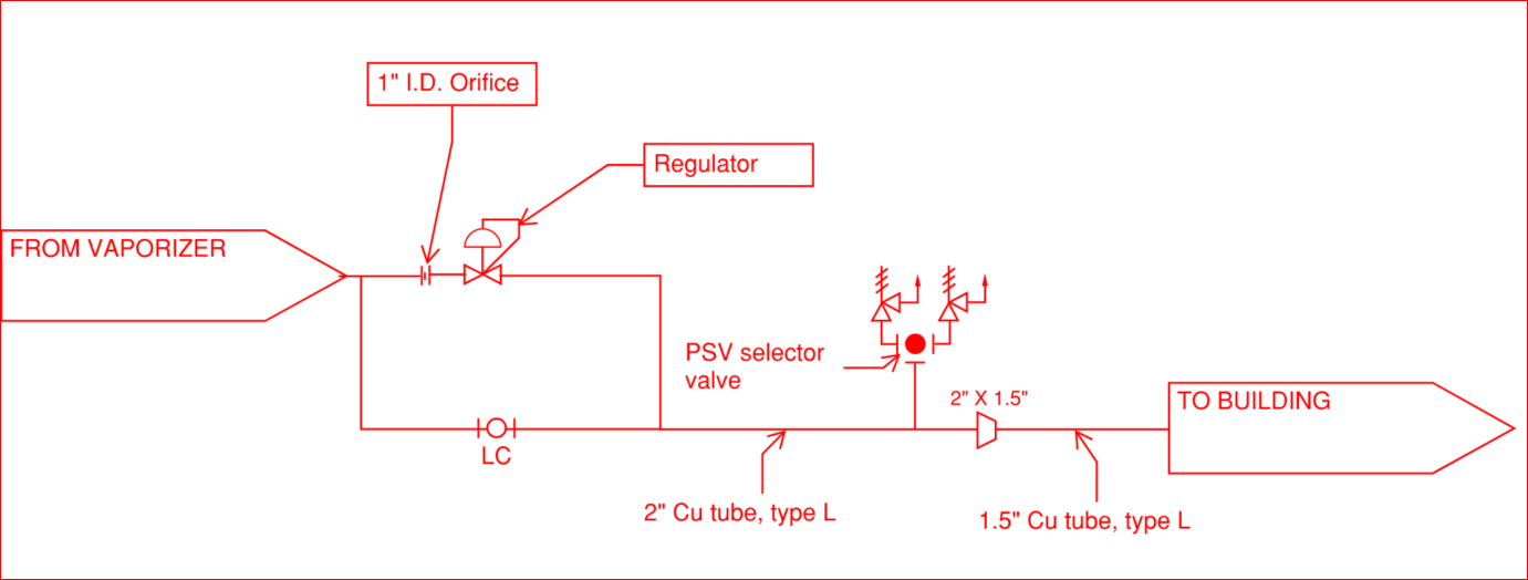
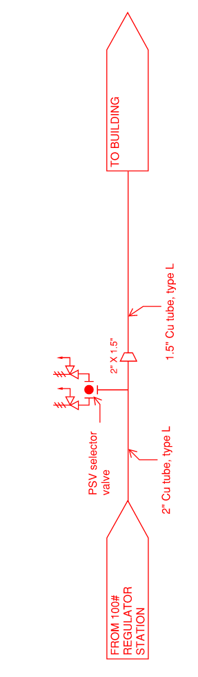
Below is a sketch of the system at large that is discussed later in the thread.
The N2 regulator will probably be the biggest restriction, by far. First pass, calculate the maximum flow through just the N2 regulator (i.e. ignore pipe and fittings). N2 source pressure in regulator inlet and PSV sizing pressure in regulator outlet.
If you get a reasonable size PSV, or you don’t get an unreasonable size PSV, I’d call it a day and go with that!
The simple equivalent length or K factor method (Crane) does not handle choked flow thru multiple diameters very well. You’d need compressible flow software. Maybe, @katmar ‘s software could handle this situation rigorously.
I agree with Latexman’s approach. If you just want to determine the PSV size you can make some simplifying assumptions. To get an accurate answer you would probably need a lot of iteration, calculating each component individually until the solution converged.
Apart from the overall flow determination, also check that if the regulator fails wide open the copper header will not be overpressurised at the upstream end. The PSV must be sized to keep the pressure here safe - not only at the inlet to the PSV. This will not be important if the PSV can be mounted directly after the regulator - which would probably be a good idea anyway and would simplify the flow calculation.
Since this isn’t the simple question I thought it would be, I will expand on my situation.
Downstream of my ambient air vaporizer is the regulator station (regulator failure Cv of 60) that the gas vendor will supply for a building distribution header. The vendor states the high pressure in the failure case is 250 psig because that is what relief valves upstream within their scope would limit the system to (and that would be 2 unrelated failures to get to this point). 250 psig is within the tube spec pressure limits. The relief valve is to generally protect the header from being much higher pressure than what is used inside the building between various user groups (labs, small scale pilot labs, etc.) The PSV setpoint is 120 psig. The desired installation is to have a selector valve for this line so the PSVs can be switched between with minial disruption to the building.
I calculated a failure mode flow demand of 41,670 lbm/hr at 32°F (9546 scfm, 68°F, 14.7 psia). When I use that demand to size a PSV via the API preliminary equations, I get a 3.52 sq.in. orifice requirement which is either a 3" or 4" valve depending on which vendor catalog I look at. This leads to the question of can I have an expansion before a selector valve that has the required PSVs, assuming that an expansion before a PSV is still not good practice even with something in between them.
If I use the average density (1.05 lbm/cu.ft.) between 250 psig and 120 psig, I get Ma = 0.46. If I use the density at 120 psig (0.87 lbm/cu.ft.), Ma = 0.68. This is why I was thinking I needed to do Fanno flow type calculations due to the large density variation I could expect in a relatively short length.
I think, given where all this will be installed, there could be around 10 ft of straight pipe with additional components (I’m at an equivalent length of 72ft all things considered) between the regulator and the PSV even if I say “minimize length”. The whole run from the regulator to the PSV setup would be 2", before reducing to connect to a 1.5" header.
My other option is to see if the gas vendor will supply the relief design, but my previous experieince is that they state that is the owner’s scope since protection of downstream elements is beyond their scope.
Hi, @jari001. The flow I got was 24% less. Take a look. Maybe, I got something wrong. Do you have x(t) of the regulator?
I see now why you may want to include the pipe and fittings. A 3-4" PSV on a 1.5-2" pipe and fittings appears nonsensical, and may get rude comments from the pipe fitters and operators.
Apologies, I typed “51670” instead of “41670”, so our calcualted flows match. I have reached out to the regualtor vendor for the x_t value. I’ve typically assumed 1 for a conservative estimate but here may be where that breaks down.
I quickly looked up a Consolidated 1905, M orifice, 4" x 6", 9637 scfm capacity.
This is unreasonable for a 1.5" - 2" line. You should sharpen the pencil and rigorously analyze it, hopefully with some good compressible flow software!
P.S. - You may find it hard to get the inlet dP under 3%. Consolidated uses 60 F as standard condition.
My company has PipeFlo Advantage available on request. I’ve requested that to see if it can handle these near sonic conditions.
I’ve reached out to the regulator manufacturer to get their input on what x(t) should be for the regulator. I’ve asked the bulk gas engineer for more details on the station and if they have provided solutions for other clients for this issue.
I looked at the pictures I had of the exisitng vaporizer and regulator setup and saw there was some type of orifice upstream of the regulator. I am hoping to get a P&ID of the proposed, new station and see if they provide an orifice as a standard item. If it’s there, that orifice would be the limiting factor even for a regulator failure in terms of the possible relief load.
Not getting to the 3% inlet loss criteria was the first “oh this gets worse” realization I had when I first started on this little quest x)
I confirmed there is an orifice, with a 1" ID with the hole increasing in diamter in the direction of flow . I used the maximum possible pressure difference (250 psig - 132 psig) to calculate the max flow rate through the orifice of 13,327 lbm/hr which is much more managable. This flow rate would be more than the vaporizer could instaneously deliver, but I think it’s my credible, conservative case.
The orifice is upstream of the regulator, so isn’t that fixing the flow through the system regardless of the downstream components? The regulator in the fail open mode allows a lot more flow so I’m not understanding how the case would get smaller.
Fixing? If the resistance to flow of one is much, much larger than the other, yes. The orifice is about 3X the resistance of the regulator based on flows (41670/13327). If 13327 lb/hr results in a PSV that can be easily accommodated, call it good. But if there are difficulties, the two resistances in series will give a smaller flow. How much smaller? Idk, that would have to be calculated.
The Pip-Flo Advantage software I have is able to do compressible flow calculations following the methods in Crane TP 410, so it is using isentropic and adiabatic flow equations. Using this software, I was able to select a 2" sch. 10 SS pipe for the inlet pipe after the regulator station to be within 3% of the set pressure (120 psig) and a 4" sch 10 SS pipe for the outlet to stay well below the 10% of the setpressure. I was able to get a Farris relief valve details to use actual flow rates.
The 4" outlet pipe is probably overly conservative, but I wasn’t getting good agreement with the software results v.s. hand calculations for 3" pipe (duct addition method where I used equivalent lengths for the various minor losses), so I figured going to 4" will definitely work from the dP perspective and I was told buying 3.5" pipe is unusual so hopefully it’s also a win from the procurement front.
Actual flow rate = 15508 lb/hr
Inlet dP = 3.4 psi (includes 1 ft of pipe, an expansion, selector valve Cv, and 90° bend into the relief valve)
Outlet dP = 6.2 psi (includes 3 ft of pipe, an expansion, 90° bend, and exit loss)
And for what it’s worth, the X_t for a Cashco DA4 spring regulator is 0.72. Got that response from the vendor’s rep for my area after someone at the factory did some calculations.