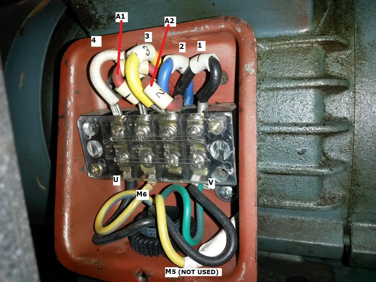
First, one of the motor wires is disconnected. It’s labeled “M5”. I can re-connect it to an unused screw on the terminal block to tidy it up. While the motor is running was there a risk that a voltage on that wire could ground out to the box?
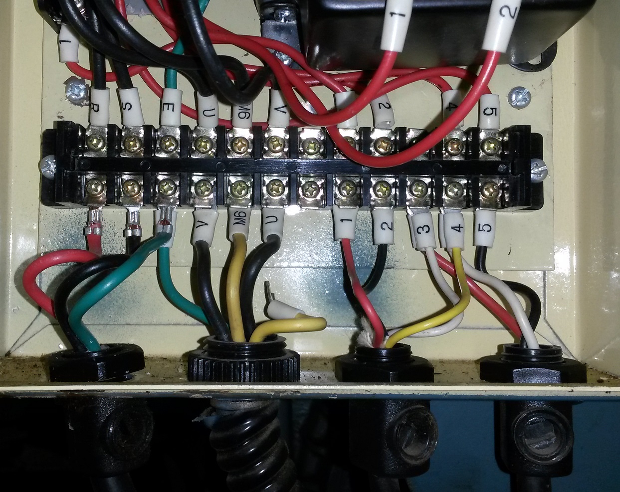
Next, the motor wires seem to be reversed. Starting from the left, the wires to the motor are V-M6-U, while the wires above are U-M6-V. Should I do something about that? If I switched V with U, would it run the opposite direction?
The motor is a 240VAC reversible, capacitor-start with a centrifugal switch.
I thought U-V-W terminology was only used on polyphase motor connections, and I don’t recognize the “M5” and “M6” labels.
It’s hard to tell from the picture, Spar.
Is that wire connected at the motor end or is it an extra core in the cable?
Does the motor start and run well now?
The motor may be based on a dual voltage, 115:230 Volt motor.
These motors typically use a 115 Volt starting winding.
When on the 230 Volt connection, one end of the start winding is connected to the center tap formed where the run windings are connected in series.
If the motor is wired in a machine such as a lathe and the machine is rated for only 230/240 Volt operation, then reversing is very easy and simple.
Only three wires are needed. Two conductors to supply 240 Volts to the run windings and one wire brought back from one end of the starting winding.
If that one wire is connected to L1, or V, the motor runs one way.
If that one wire is connected to L2, or U, the motor runs the other way.
What HP is the motor?
Howdy
Sorry for the limited information. The lathe is set in place and leveled where it is, which makes the motor inaccessible now, unless I’m prepared to move the lathe again. Like you, I want to get at the motor’s connections box, but the effort to move it and then re-locate the lathe is pretty high. The question is a bit academic since, yes, it runs OK now.
I don’t know the HP of the motor for certain. There’s no dataplate on the motor. My guess is it’s 2HP.
It’s obviously capacitor-start and I can here the centrifugal switch click during starts and stops.
Also a good question that I didn’t consider: yes it could have a 115V start. That would explain a 115V measurement I saw while prodding it with my multimeter. I was puzzled by that at first, thinking it is only getting 230V. Unfortunately my DMM’s are too slow to display a value during the 1-second it takes for the motor to spin up and the centrifugal switch to open, so I have only been reading the voltages while running. Maybe an analog meter will respond fast enough to catch the switch opening and I can figure out which wire feeds the start winding.
It is probably a dual voltage motor as I suggested.
2 HP is a little much for 115 Volts, so it is reasonable that it may be rated at only 230 Volts.
Is there continuity from that free wire to any other wires?
Testing.
With the motor running, check between M6 to V and between M6 to U.
I suspect that you will find ) V and 240 V, and with the motor running in the opposite direction the voltage readings will be reversed.
The coin just dropped on this.
I’m also reading through Roserberg’s book again. I mistakenly flipped too far and got mixed up in the “two-speed” motors and now that I’m back at the “two-voltage” motors what I’m seeing makes much more sense and lines up with what you’re saying.
With a better picture in my head I can line up what my meters tell me. Thanks!
Note: Rosenberg includes examples of split start windings as you described AND examples of split run windings, where the reversing is done by flipping the run winding connections rather than the start windings. That seems like it would hurt the performance 99% of the time but guarantee higher torque on starting.
My Rosenberg’s has gone missing over the years.
Can you scan that page?
There must be another factor in play here.
Reversing is normally dependent on the relative connections between the start and run windings, and it doesn’t matter which is reversed.
It is generally easier physically to switch the start winding.
Curiosity motivated me to move the lathe, despite the effort.
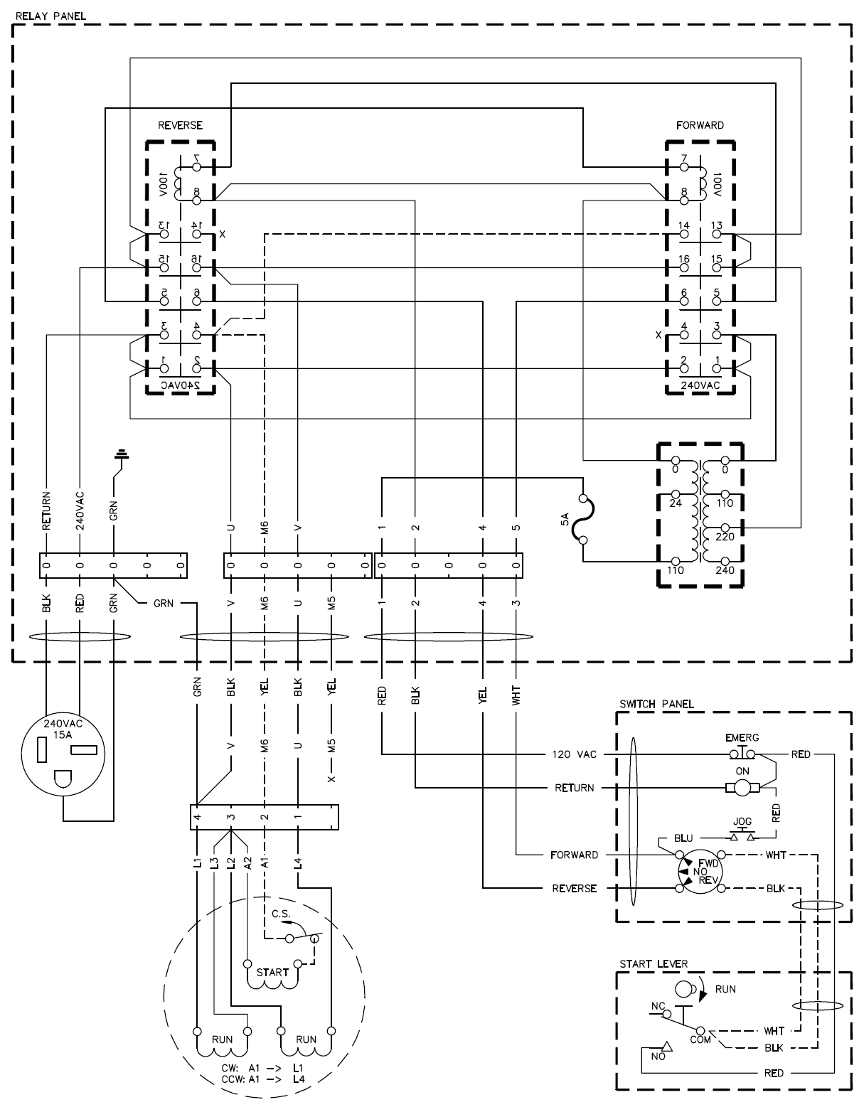
With the cover off the motor’s connection box (and this one has a useful connection diagram inside it) it all became clear. As you expected it to be at first: switching the start winding to the L1 or L2 line will run the motor CW or CCW as you choose. The motor does have high and low-voltage connections, and this is used to advantage allowing the start winding to run on 115V in either case, and just needs to be flipped from L1 to L4 (as they’re numbered on this motor). The other end is connected to the “middle” of the run winding when operating in high voltage connection, like it is now.
No, thank you for steering me in the right direction.
I can also tell now that swapping the U and V wires would reverse the operation of the motor.
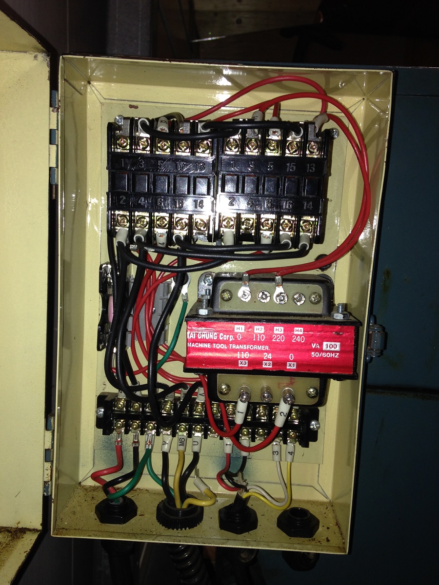
This would be a simple fix to the sticky forward relay, by making it the (less often used) reverse relay.
I have the wiring reversed now, and everything works wonderfully. Starts are still immediate like they were, but now stop are immediate, too, and in both directions.
I’ve plotted the whole electrical control box schematic now. The usual thing: with wires all tightly packed together, I can’t make sense of wiring in the box until I’ve drawn out the schematic and made it tidy.
Thank you very much for the scan, Spar.
I don’t remember ever identifying one of those motors in the field and have not read about them.
I guess I’m never too old for something new.
I should have been more careful of my “Rosenberg’s”
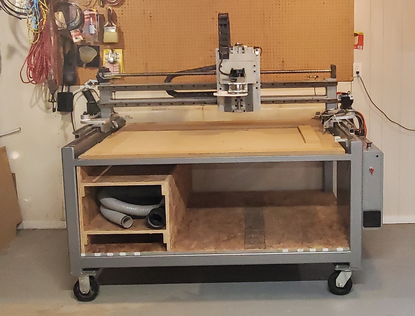
This CNC router was a DIY project of another engineer who lives near me. He said he’s moving across the country when he retires, and can’t take the big shop tools with him. Being a DIY project, he couldn’t price it very high, so I’m just thrilled that waiting for the right deal to come along has worked out.
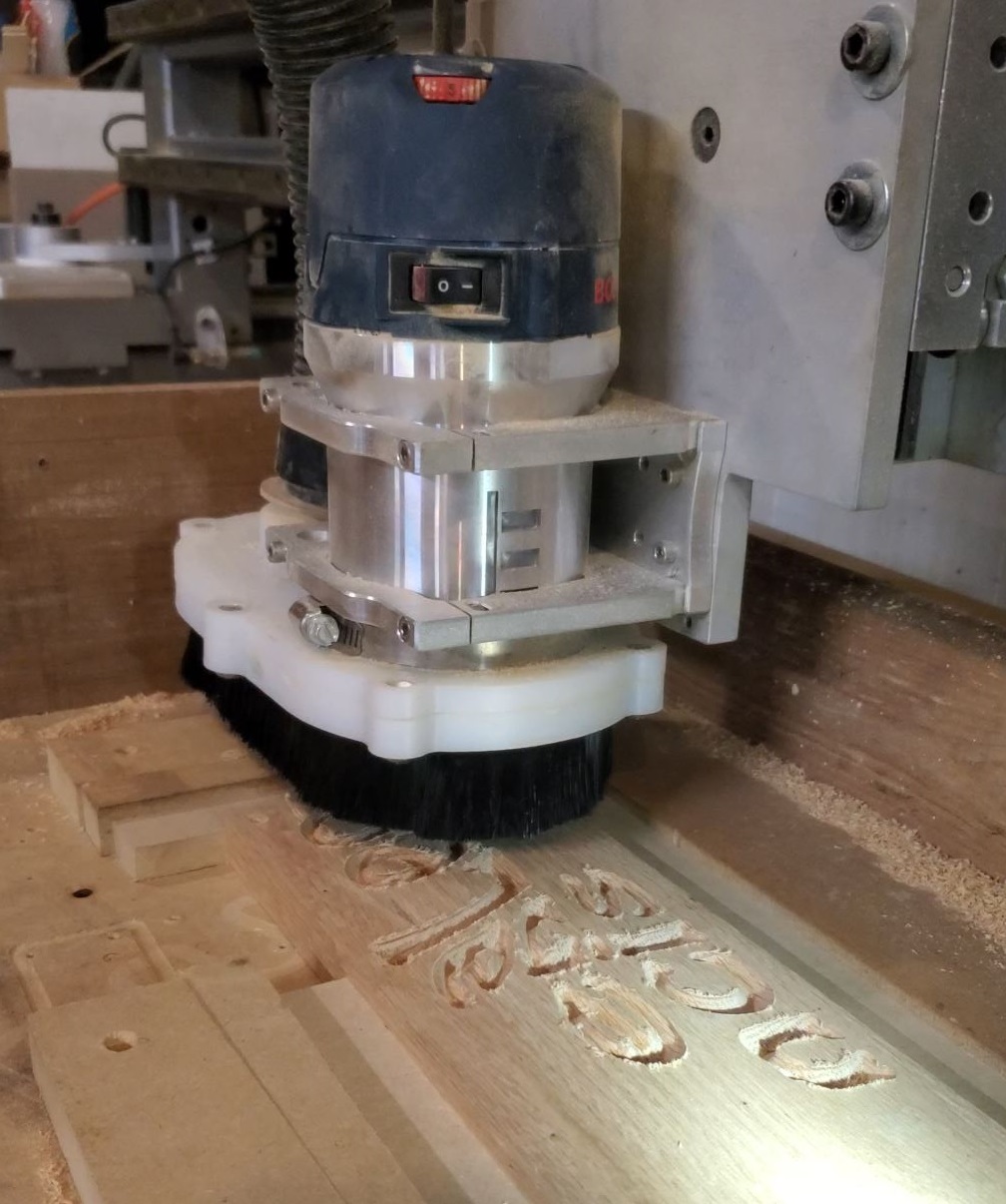
Tonight I cut a view pieces of wood (etch-a-sketch style) just to demonstrate that it’s working. There’s a lot more to do before it’s set up properly to make “real” parts.
I’ve run some test patterns (without a cutting tool) and I have actually cut some wood pieces with simple “jog” commands. Right now, buying cutting tools like router bits and end mills so that I can use it for real.
You can see it on wheels, because I’m probably going to finish the shop ceiling and insulate it, meaning I have to move stuff around for a while. I won’t be using this router seriously for a couple of months.